Front Panel, Patch Bay & Buss Link
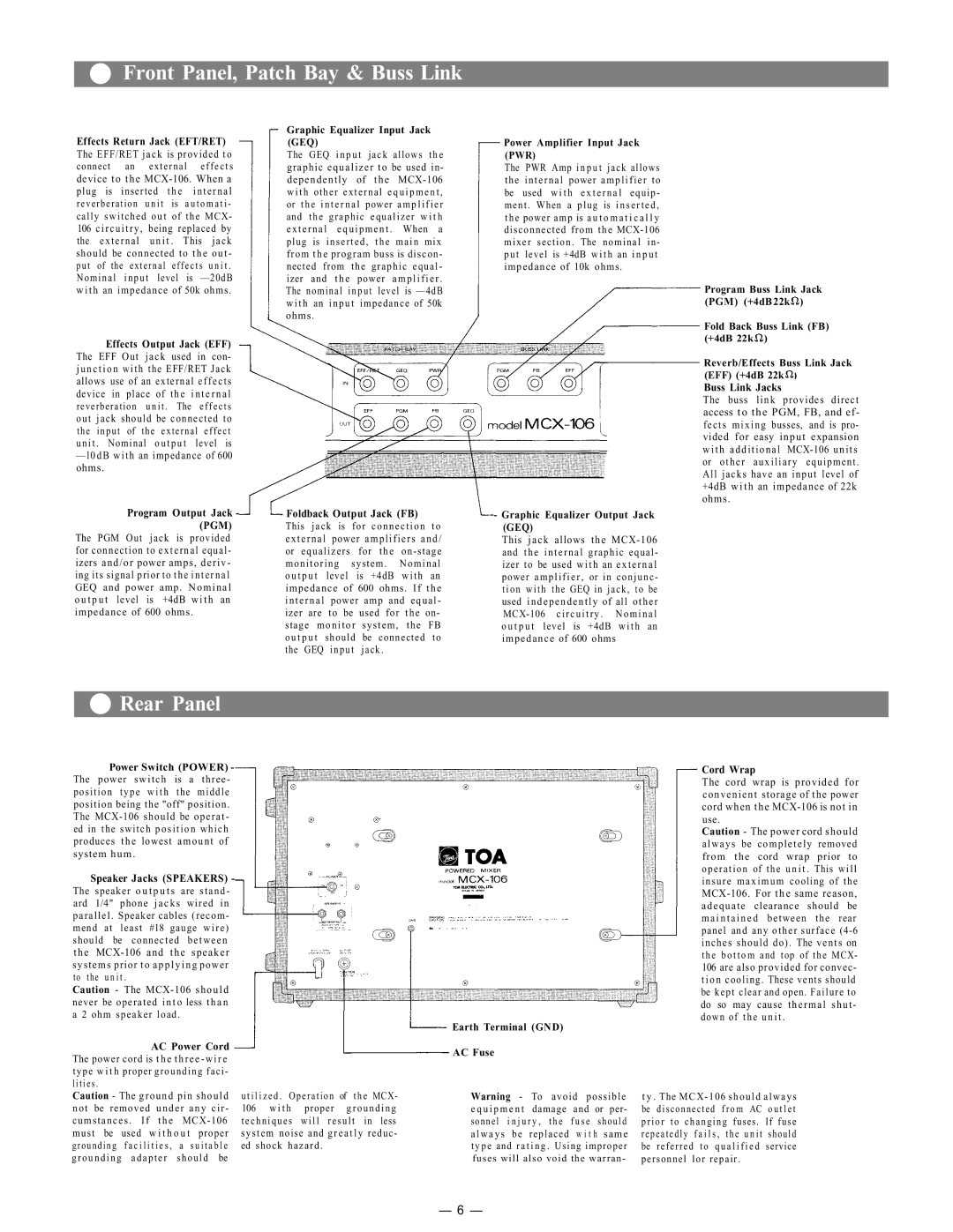
Effects Return Jack (EFT/RET)
The EFF/RET jack is provided to
connect an external effects
device to the
plug is inserted | t h e | internal |
reverberation u n i t | is | a u t o m a t i - |
cally switched out of the MCX-
106 circuitry, being replaced by the external u n i t . This jack
should be connected to the out - put of the external effects u n i t .
Nominal input level is
w i t h an impedance of 50k ohms.
Effects Output Jack (EFF)
The EFF Out jack used in con- j u n c t i o n with the EFF/RET Jack allows use of an external effects
device in place of | the i n t e r n a l |
reverberation unit . | The effects |
out jack should be connected to the input of the external effect unit . Nominal o u t p u t level is
—l0dB with an impedance of 600 ohms.
Graphic Equalizer Input Jack (GEQ)
The GEQ i n p u t jack allows t h e
graphic equalizer to be used in-
dependently of the
w i t h other external e q u i p m e n t ,
or the i n t e r n a l | power | a m p l i f i e r | |
and the | graphic | equalizer w i t h | |
external | equipment . | When a | |
plug is inserted, the main mix from the program buss is discon- nected from the graphic equal- izer and the power amplifier .
The nominal input level is
w i t h an input impedance of 50k ohms.
Power Amplifier Input Jack (PWR)
The PWR Amp i n p u t jack allows
the internal power amplifier to be used w i t h e x t e r n a l equip- ment . When a plug is inserted, the power amp is a u t o m a t i c a l l y disconnected from the
Program Buss Link Jack (PGM) (+4dB 22k![]() )
)
Fold Back Buss Link (FB)
(+4dB 22k![]() )
)
Reverb/Effects Buss Link Jack (EFF) (+4dB 22k![]() )
)
Buss Link Jacks
The buss link provides direct access to the PGM, FB, and ef- fects mixing busses, and is pro- vided for easy input expansion w i t h additional
Program Output Jack - (PGM)
The PGM Out jack is provided for connection to external equal-
izers and/or power amps, deriv-
ing its signal prior to the internal
GEQ and power amp. Nominal
o u t p u t level is +4dB with an
impedance of 600 ohms.
-Foldback Output Jack (FB) This jack is for connection to external power amplifiers and/ or equalizers for the
o u t p u t level is +4dB with an
impedance of 600 ohms. If the internal power amp and equal - izer are to be used for the on-
stage monitor | system, the | FB | |
o u t p u t | should | be connected | to |
the GEQ | input | jack. |
|
-Graphic Equalizer Output Jack (GEQ)
This jack allows the
 Rear Panel
Power Switch (POWER) -
The power switch is a three-
position type w i t h the middle
position being the "off" position.
The
ed in the switch position which
produces the lowest amount of
system hum.
Speaker Jacks (SPEAKERS) -
The speaker o u t p u t s are stand - ard 1/4" phone jacks wired in parallel. Speaker cables (recom- mend at least #18 gauge wire) should be connected between
the
systems prior to applying power |
|
|
| ||||
to the | u n i t . |
|
|
|
|
| |
Caution - The |
|
|
| ||||
never be operated i n t o less t h a n |
|
|
| ||||
a 2 ohm speaker load. |
|
|
|
| |||
|
| AC Power Cord |
|
|
| ||
The power cord is t h e three - wire |
|
|
| ||||
type w i t h proper grounding faci - |
|
|
| ||||
lities . |
|
|
|
|
|
|
|
Caution - The ground pin should | u t i l i z e d . Operation | of the MCX- | |||||
not be removed under any cir - | 106 | w i t h proper | grounding | ||||
cumstances . If the | techniques will result in less | ||||||
must | be | used w i t h o u t | proper | system noise and greatly reduc- | |||
grounding | f a c i l i t i e s , | a | s u i t a b l e | ed | shock hazard . |
| |
grounding | adapter | should be |
|
|
| ||
Earth Terminal (GND)
AC Fuse
Warning - | To | avoid possible | ||
e q u i p m e n t | damage | and or per- | ||
sonnel | i n j u r y , | t h e | f u s e should | |
a l w a y s | be | replaced | w i t h same | |
t y p e and r a t i n g . Using improper
fuses will also void the warran-
Cord Wrap
The cord wrap is provided for convenient storage of the power cord when the
use.
Caution - The power cord should
always be completely removed from the cord wrap prior to operation of the u n i t . This will insure maximum cooling of the
adequate clearance should be m a i n t a i n e d between the rear panel and any other surface
inches should do). The vents on
the b o t t o m and top of the MCX-
106 are also provided for convec-
t i o n cooling. These vents should
be kept clear and open. Failure to
do so may cause thermal shut - down of the u n i t .
t y . The
repeatedly | f a i l s , the u n i t | should |
be referred | to q u a l i f i e d | service |
personnel lor repair . |
| |
— 6 —