
RVDD336R, CRVDD330R, CRVDD336R, CRVDD345R, RVDD345R specifications
The Viking CRVDD336R, RVDD345R, RVDD336R, CRVDD330R, and RVDD330R represent a series of advanced HVAC units designed to provide efficient cooling and heating solutions for a variety of commercial and residential applications. These models stand out due to their innovative technologies, energy efficiency, and user-friendly features.One of the principal characteristics of these units is their robust design, enabling them to withstand harsh environmental conditions while maintaining performance consistency. Each model features a high-performance compressor and a well-engineered fan system that promotes optimal airflow. This ensures that indoor spaces are kept at comfortable temperatures while minimizing energy consumption.
Energy efficiency is a key highlight of the Viking line. Many of these models come equipped with inverter technology, which adjusts the compressor speed based on the cooling or heating demand. This not only lowers energy consumption but also reduces wear and tear on components, extending the lifespan of the system.
Additionally, the Viking CRVDD and RVDD series incorporate advanced control systems that enhance user experience. These controls allow for precise temperature settings and programmable schedules, providing flexibility to adapt to varying occupancy patterns. Moreover, some units are compatible with smart home systems, enabling remote access and management through mobile applications.
In terms of installation, these models are designed for versatility. They can be installed in various configurations, including ducted and ductless options, making them suitable for different building layouts. Their compact size also means they can fit in tight spaces while still providing powerful heating and cooling capabilities.
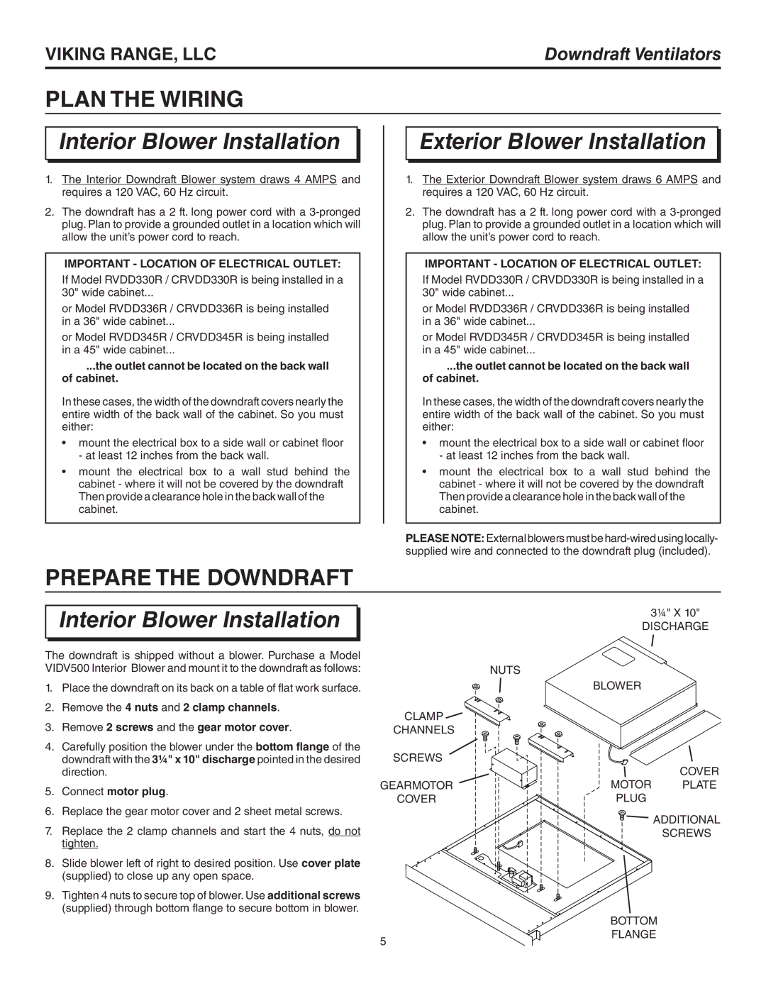
Maintenance is made easy with these units. Users can perform regular checks and service with minimal hassle, thanks to accessible components designed for quick inspections and replacements. Many models feature self-diagnosis capabilities, alerting users to potential issues before they escalate, further minimizing downtime.
Overall, the Viking CRVDD336R, RVDD345R, RVDD336R, CRVDD330R, and RVDD330R units are engineered to meet the demanding needs of today’s users. Their combination of efficiency, flexibility, and advanced technology positions them as excellent choices for anyone looking to upgrade their HVAC systems. With a strong focus on performance and sustainability, these models are an investment in comfort and reliability for years to come.