Assembly
Figure 9
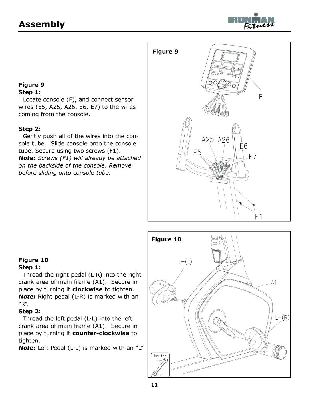
Step 1:
Locate console (F), and connect sensor wires (E5, A25, A26, E6, E7) to the wires coming from the console.
Step 2:
Gently push all of the wires into the con- sole tube. Slide console onto the console tube. Secure using two screws (F1).
Note: Screws (F1) will already be attached on the backside of the console. Remove before sliding onto console tube.
Figure 9
F
Figure 10
Step 1:
Thread the right pedal
Step 2:
Thread the left pedal
Note: Left Pedal
Figure 10 |
11 |