Assembly
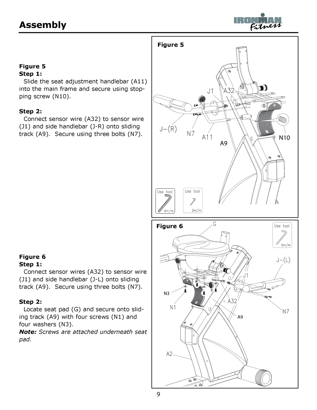
Figure 5
Step 1:
Slide the seat adjustment handlebar (A11) into the main frame and secure using stop- ping screw (N10).
Step 2:
Connect sensor wire (A32) to sensor wire (J1) and side handlebar
Figure 5
A9
N10
Figure 6
Step 1:
Connect sensor wires (A32) to sensor wire (J1) and side handlebar
Step 2:
Locate seat pad (G) and secure onto slid- ing track (A9) with four screws (N1) and four washers (N3).
Note: Screws are attached underneath seat pad.
Figure 6 |
N3 |
A9 |