IP7330 specifications
Vivotek IP7330 is a versatile and high-performance network camera designed for easy integration into various security setups. This camera is well-suited for both indoor and outdoor applications, making it an ideal choice for surveillance in diverse environments.One of the main features of the Vivotek IP7330 is its high-resolution imaging capability. It provides users with 1.3 megapixels of resolution, delivering clear and detailed images. This ensures that critical details are captured, allowing for effective monitoring and evidence gathering when necessary. The camera also supports H.264 and MJPEG compression formats, which optimize bandwidth and storage requirements without compromising image quality.
Another significant characteristic of the IP7330 is its advanced day/night functionality. Equipped with a removable IR-cut filter, this camera automatically switches between color and monochrome video based on lighting conditions. This feature guarantees optimal performance around the clock, ensuring continuous surveillance regardless of the time of day.
The Vivotek IP7330 also incorporates smart detection features that enhance security monitoring. These include motion detection and tamper detection alerts, which notify users of any suspicious activities. With the ability to trigger automated responses, the camera contributes to proactive surveillance management.
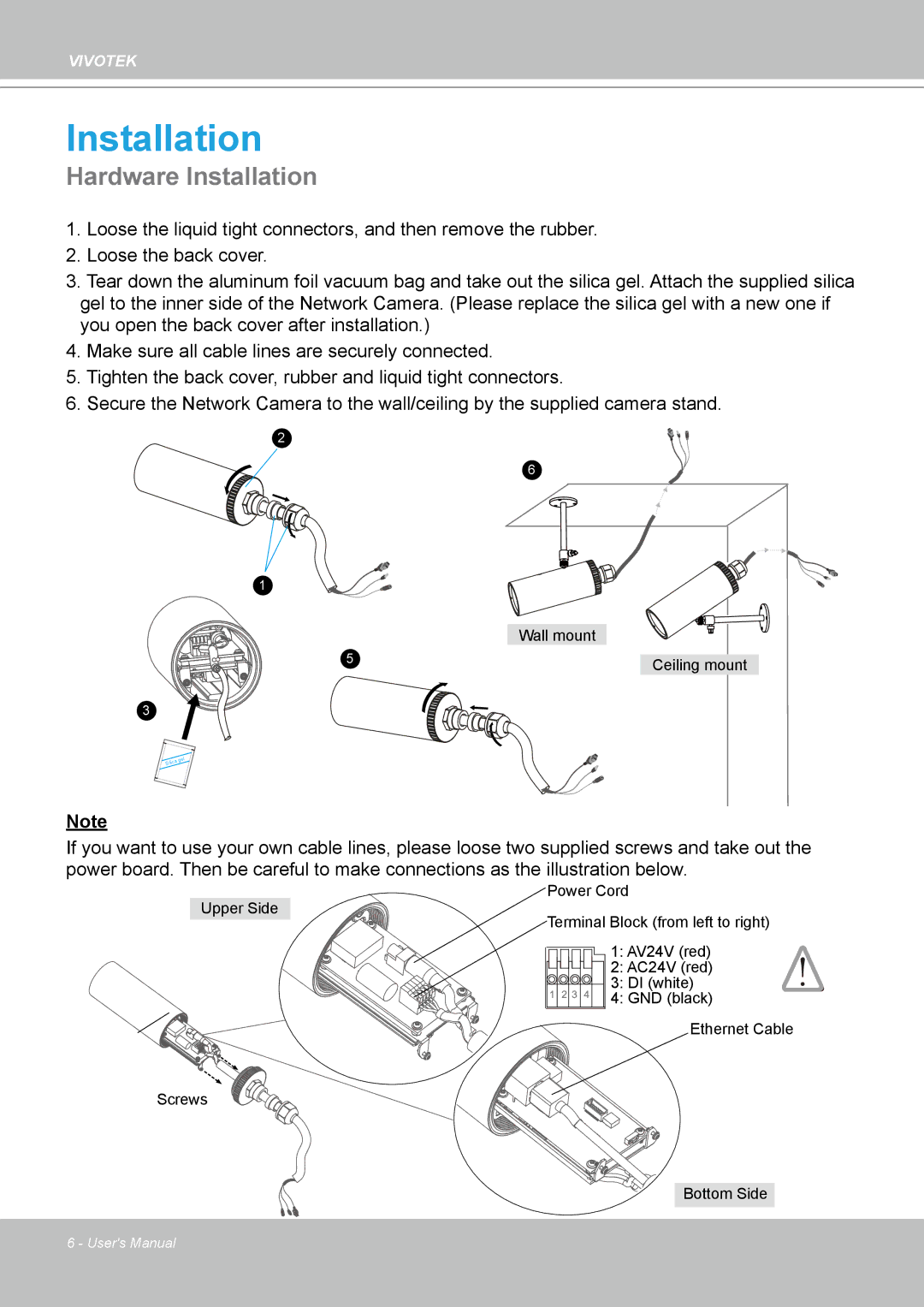
Additionally, the IP7330 is designed with user-friendly installation in mind. The camera comes with Power over Ethernet (PoE) technology, allowing for easy deployment by using a single cable for both power and data transmission. This simplifies installation and reduces cabling requirements, making it a practical choice for various settings.
Durability is another key characteristic of the Vivotek IP7330. The camera is built to withstand harsh environments with an IP66-rated housing, which protects it against dust and water ingress. This robustness ensures reliable operation even in challenging weather conditions.
Overall, the Vivotek IP7330 combines high-performance imaging, intelligent monitoring features, and user-friendly deployment options. Its advanced technologies make it a strong contender in the IP camera market, appealing to both residential and commercial users looking for reliable surveillance solutions.

