VIVOTEK
Network Deployment
Setting up the Network Camera over the Internet
This section explains how to configure the Network Camera to an Internet connection.
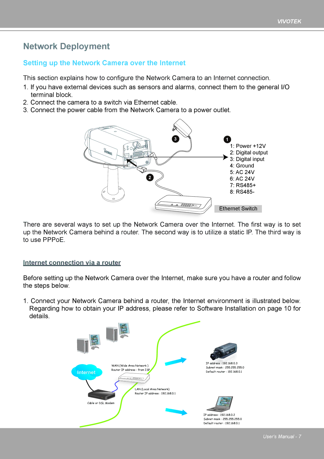
1.If you have external devices such as sensors and alarms, connect them to the general I/O terminal block.
2.Connect the camera to a switch via Ethernet cable.
3.Connect the power cable from the Network Camera to a power outlet.
3 | 1 |
| 1: Power +12V |
| 2: Digital output |
| 3: Digital input |
| 4: Ground |
2 | 5: AC 24V |
6: AC 24V | |
| 7: RS485+ |
| 8: RS485- |
Ethernet Switch
There are several ways to set up the Network Camera over the Internet. The first way is to set up the Network Camera behind a router. The second way is to utilize a static IP. The third way is to use PPPoE.
Internet connection via a router
Before setting up the Network Camera over the Internet, make sure you have a router and follow the steps below.
1.Connect your Network Camera behind a router, the Internet environment is illustrated below. Regarding how to obtain your IP address, please refer to Software Installation on page 10 for details.
Internet
WAN (Wide Area Network ) | IP address : 192.168.0.3 | |
Subnet mask : 255.255.255.0 | ||
Router IP address : from ISP | ||
Default router : 192.168.0.1 | ||
| ||
LAN (Local Area Network) |
| |
Router IP address : 192.168.0.1 |
|
Cable or DSL Modem
IP address : 192.168.0.2
Subnet mask : 255.255.255.0
Default router : 192.168.0.1
User's Manual - 7