Optional Accessories
� � � �
�
UHF Wireless Channels (optional accessory)
You can add up to four UHF wireless microphone modules (sold separately) to use with the
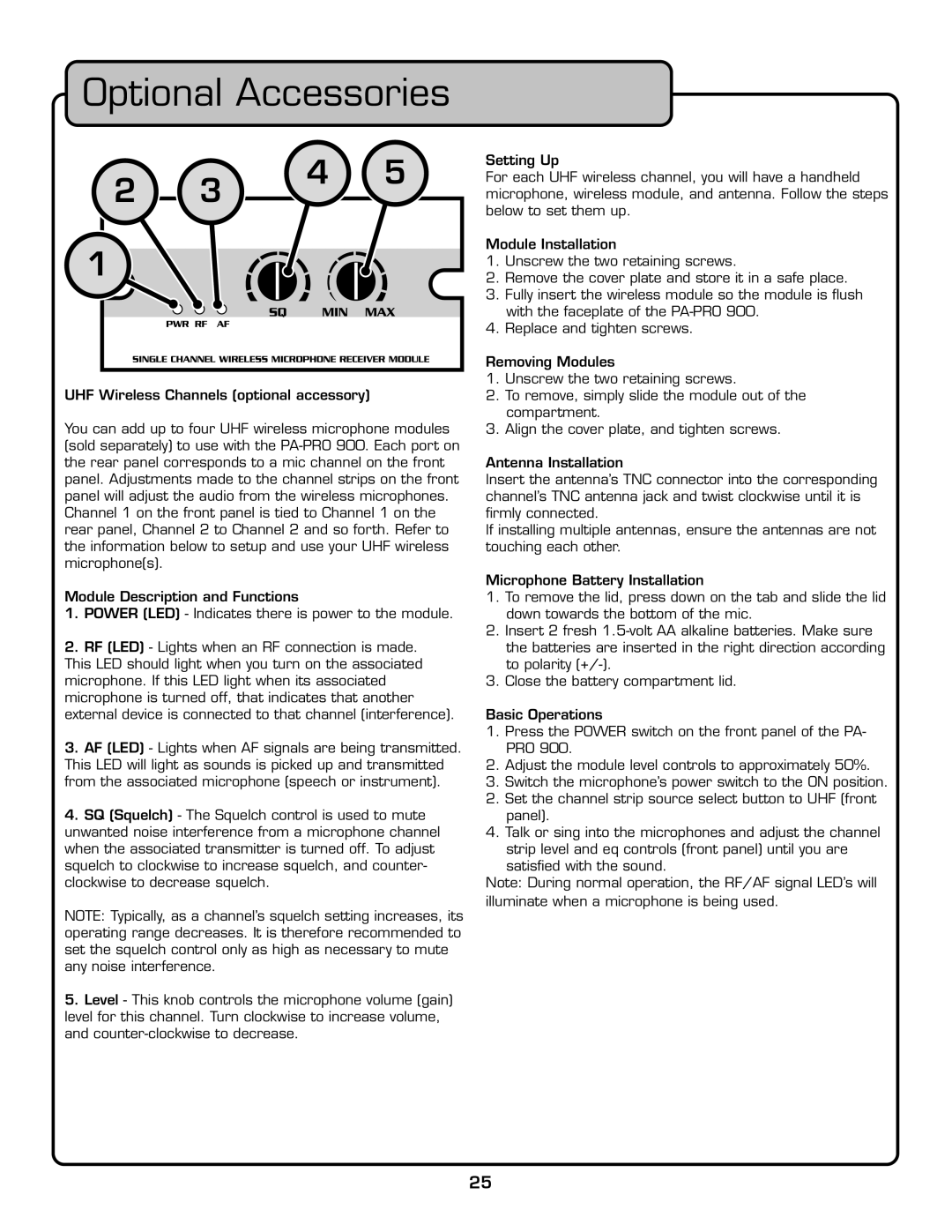
Module Description and Functions
1.POWER (LED) - Indicates there is power to the module.
2.RF (LED) - Lights when an RF connection is made.
This LED should light when you turn on the associated microphone. If this LED light when its associated microphone is turned off, that indicates that another external device is connected to that channel (interference).
3.AF (LED) - Lights when AF signals are being transmitted. This LED will light as sounds is picked up and transmitted from the associated microphone (speech or instrument).
4.SQ (Squelch) - The Squelch control is used to mute unwanted noise interference from a microphone channel when the associated transmitter is turned off. To adjust squelch to clockwise to increase squelch, and counter- clockwise to decrease squelch.
NOTE: Typically, as a channel’s squelch setting increases, its operating range decreases. It is therefore recommended to set the squelch control only as high as necessary to mute any noise interference.
5.Level - This knob controls the microphone volume (gain) level for this channel. Turn clockwise to increase volume, and
Setting Up
For each UHF wireless channel, you will have a handheld microphone, wireless module, and antenna. Follow the steps below to set them up.
Module Installation
1.Unscrew the two retaining screws.
2.Remove the cover plate and store it in a safe place.
3.Fully insert the wireless module so the module is fl ush with the faceplate of the
4.Replace and tighten screws.
Removing Modules
1.Unscrew the two retaining screws.
2.To remove, simply slide the module out of the compartment.
3.Align the cover plate, and tighten screws.
Antenna Installation
Insert the antenna’s TNC connector into the corresponding channel’s TNC antenna jack and twist clockwise until it is
fi rmly connected.
If installing multiple antennas, ensure the antennas are not touching each other.
Microphone Battery Installation
1.To remove the lid, press down on the tab and slide the lid down towards the bottom of the mic.
2.Insert 2 fresh
3.Close the battery compartment lid.
Basic Operations
1.Press the POWER switch on the front panel of the PA- PRO 900.
2.Adjust the module level controls to approximately 50%.
3.Switch the microphone’s power switch to the ON position.
2.Set the channel strip source select button to UHF (front panel).
4.Talk or sing into the microphones and adjust the channel
strip level and eq controls (front panel) until you are satisfi ed with the sound.
Note: During normal operation, the RF/AF signal LED’s will illuminate when a microphone is being used.
25