Rear Panel Features
| � | � | � |
� | � |
| � |
�
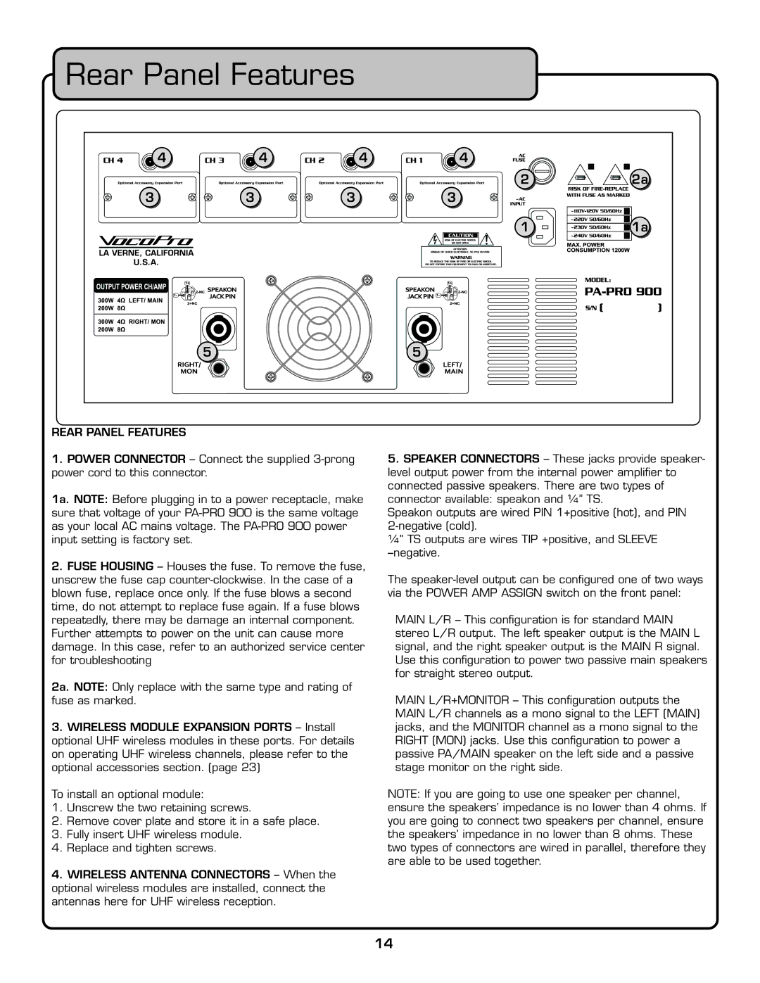
REAR PANEL FEATURES
1.POWER CONNECTOR – Connect the supplied
1a. NOTE: Before plugging in to a power receptacle, make sure that voltage of your
2.FUSE HOUSING – Houses the fuse. To remove the fuse, unscrew the fuse cap
2a. NOTE: Only replace with the same type and rating of fuse as marked.
3.WIRELESS MODULE EXPANSION PORTS – Install optional UHF wireless modules in these ports. For details on operating UHF wireless channels, please refer to the optional accessories section. (page 23)
To install an optional module:
1.Unscrew the two retaining screws.
2.Remove cover plate and store it in a safe place.
3.Fully insert UHF wireless module.
4.Replace and tighten screws.
4.WIRELESS ANTENNA CONNECTORS – When the optional wireless modules are installed, connect the antennas here for UHF wireless reception.
� |
|
� | �� |
� |
|
�![]()
![]() ��
��
�
5.SPEAKER CONNECTORS – These jacks provide speaker- level output power from the internal power amplifi er to connected passive speakers. There are two types of connector available: speakon and ¼” TS.
Speakon outputs are wired PIN 1+positive (hot), and PIN
¼” TS outputs are wires TIP +positive, and SLEEVE
The
MAIN L/R – This confi guration is for standard MAIN stereo L/R output. The left speaker output is the MAIN L signal, and the right speaker output is the MAIN R signal. Use this confi guration to power two passive main speakers for straight stereo output.
MAIN L/R+MONITOR – This confi guration outputs the MAIN L/R channels as a mono signal to the LEFT (MAIN) jacks, and the MONITOR channel as a mono signal to the RIGHT (MON) jacks. Use this confi guration to power a passive PA/MAIN speaker on the left side and a passive stage monitor on the right side.
NOTE: If you are going to use one speaker per channel, ensure the speakers’ impedance is no lower than 4 ohms. If you are going to connect two speakers per channel, ensure the speakers’ impedance in no lower than 8 ohms. These two types of connectors are wired in parallel, therefore they are able to be used together.
14