WALL MOUNTING | THE LCD DISPLAY |
|
| ||
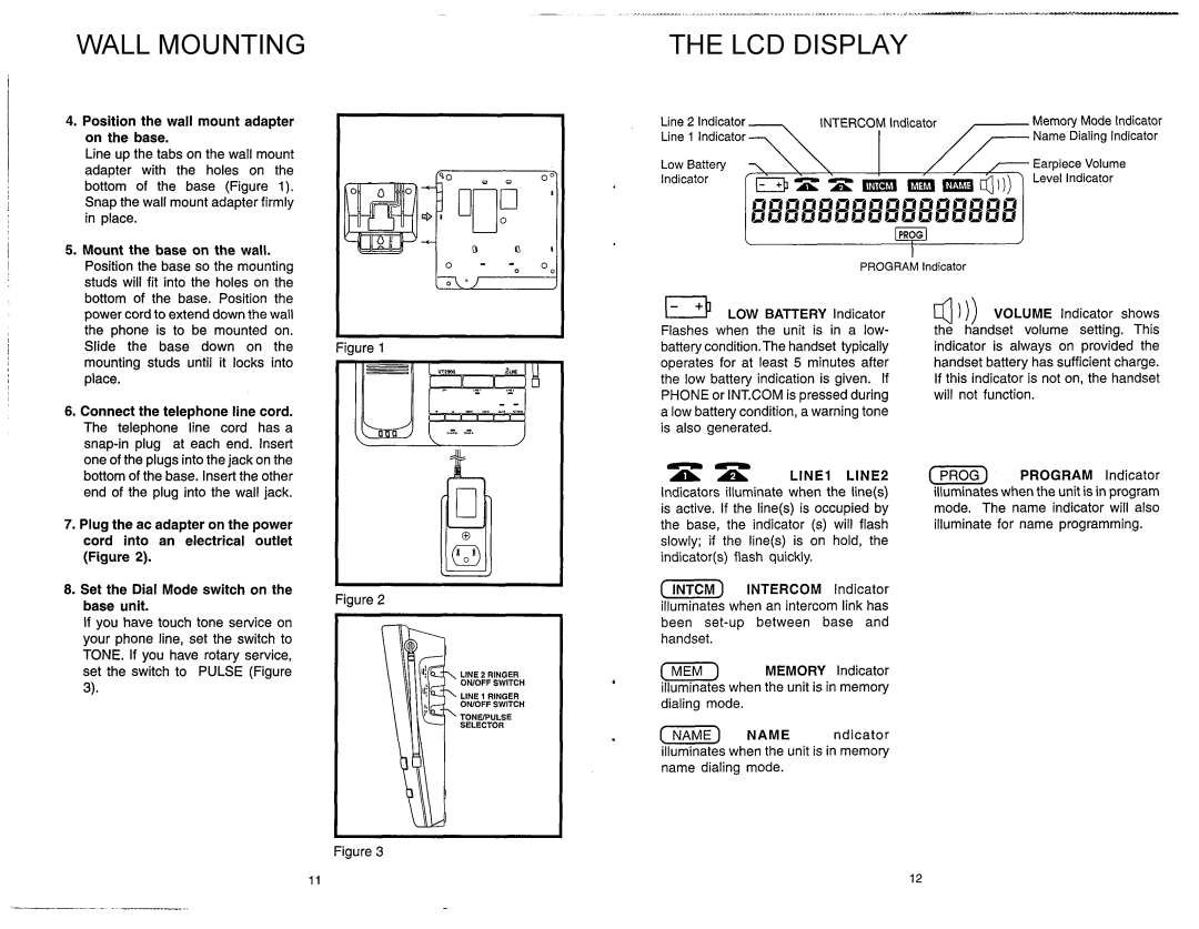
4. Position the wall mount adapter | Line 2 Indicator | INTERCOMIndicator |
| Memory Mode Indicator | |
on the base. | Line 1 l n d i c a t o r 7 |
|
|
| Name Dialing Indicator |
| I | ,- | |||
Line up the tabs on the wall mount | 7 |
|
| ||
adapter with the holes on the | Low Battery 7 \ \ |
| 7Earpiece Volume | ||
bottom of the base (Figure 1). | Indicator |
|
|
| Level Indicator |
|
|
|
|
| |
Snap the wall mount adapter firmly in place.
1
I
5. Mount the base on the wall. |
Position the base so the mounting |
studs will fit into the holes on the |
PROGRAM lndicator
i
I
I
I
bottom of the base. Position the |
power cordto extend down the wall |
the phone is to be mounted on. |
Slide the base down on the mounting studs until it locks into
place.
6. Connect the telephone line cord. |
The telephone line cord has a |
one of the plugs into the jack on the |
.
Figure 1
LOW BATTERY lndicator Flashes when the unit is in a low- battery condition.Thehandset typically operates for at least 5 minutes after the low battery indication is given. If PHONE or INT.COM is pressedduring
alow battery condition, a warning tone is also generated.
4 ) )) VOLUME lndicator shows the handset volume setting. This indicator is always on provided the handset battery has sufficient charge. If this indicator is not on, the handset will not function.
bottom of the base. Insertthe other |
end of the plug into the wall jack. |
7. Plug the ac adapter on the power cord into an electrical outlet (Figure 2).
8.Set the Dial Mode switch on the base unit.
If you have touch tone service on your phone line, set the switch to TONE. If you have rotary service, set the switch to PULSE (Figure
3).
Figure 2
|
| nn | LINE2 | |
|
| A A | LINE1 | |
|
| Indicators illuminate when the line(s) | ||
|
| is active. If the line(s) is occupied by | ||
|
| the base, the indicator (s) will flash | ||
|
| slowly; if the line(s) is on hold, the | ||
|
| indicator(s) flash quickly. |
| |
|
| [m)INTERCOM | lndicator | |
|
| illuminates when an intercom link has | ||
|
| been | ||
|
| handset. |
|
|
LlNE 2 RINGER |
| [m) MEMORY | Indicator | |
ONlOFF SWITCH |
| illuminateswhen the unit is in memory | ||
LlNE 1 RINGER |
| |||
| dialing mode. |
|
| |
OWOFF SWITCH |
|
|
| |
TONEPULSE | . |
|
|
|
SELECTOR | (NAME) | NAME | ndicator | |
| ||||
illuminateswhen the unit is in memory name dialing mode.
( PROGRAM Indicator illuminateswhen the unit is in program mode. The name indicator will also illuminate for name programming.
Figure 3
