RUI/Gateway & DeviceNetTM
Configuration & Ladder Logic Example
Using an
19.The gateway instance represents the
gateway instance simply turns on that particular gateway where there is a direct correlation between gateway instance 1 and
The CIP offset allows for the PLC or any master on the DeviceNetTM side to read or write the same member from any of the four controllers on the Standard Bus network via an explicit message.
Configuring the DeviceNetTM Scanner (1769-SDN) Using RSLogix 5000
20.In the examples that follow please note that the PLC being used is a CompactLogix L32E. If using other PLCs the steps will vary slightly but the overall concepts will be the same. As you might guess some configuration is required on the PLC side prior to getting started with the programming.
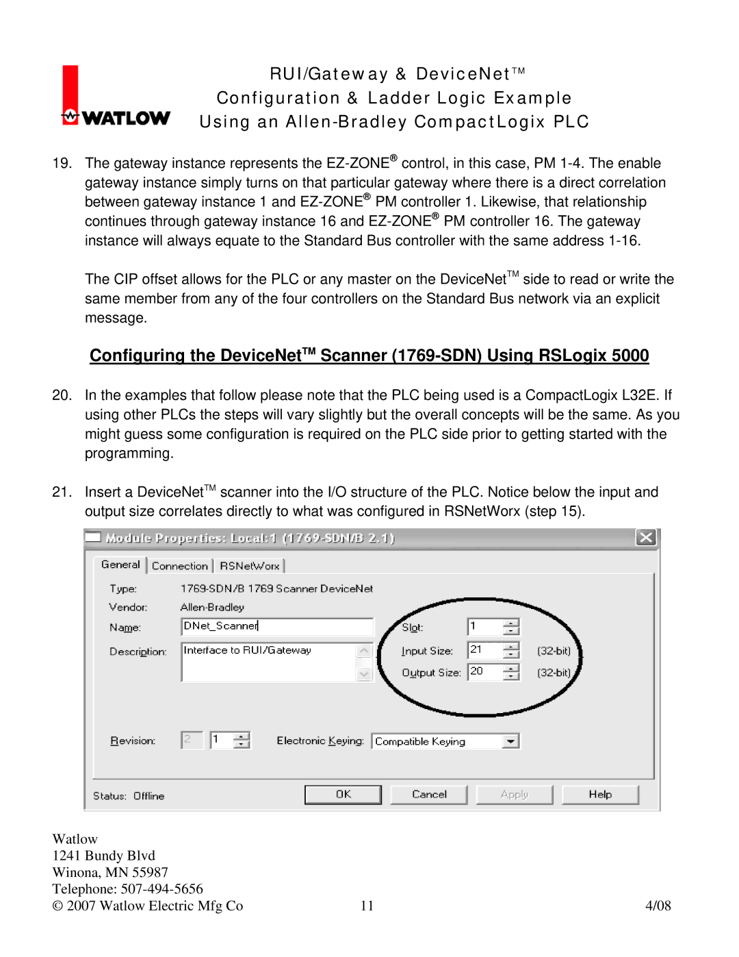
21.Insert a DeviceNetTM scanner into the I/O structure of the PLC. Notice below the input and output size correlates directly to what was configured in RSNetWorx (step 15).
Watlow |
|
|
1241 Bundy Blvd |
|
|
Winona, MN 55987 |
|
|
Telephone: |
|
|
© 2007 Watlow Electric Mfg Co | 11 | 4/08 |