RUI/Gateway & DeviceNetTM
Configuration & Ladder Logic Example
Using an
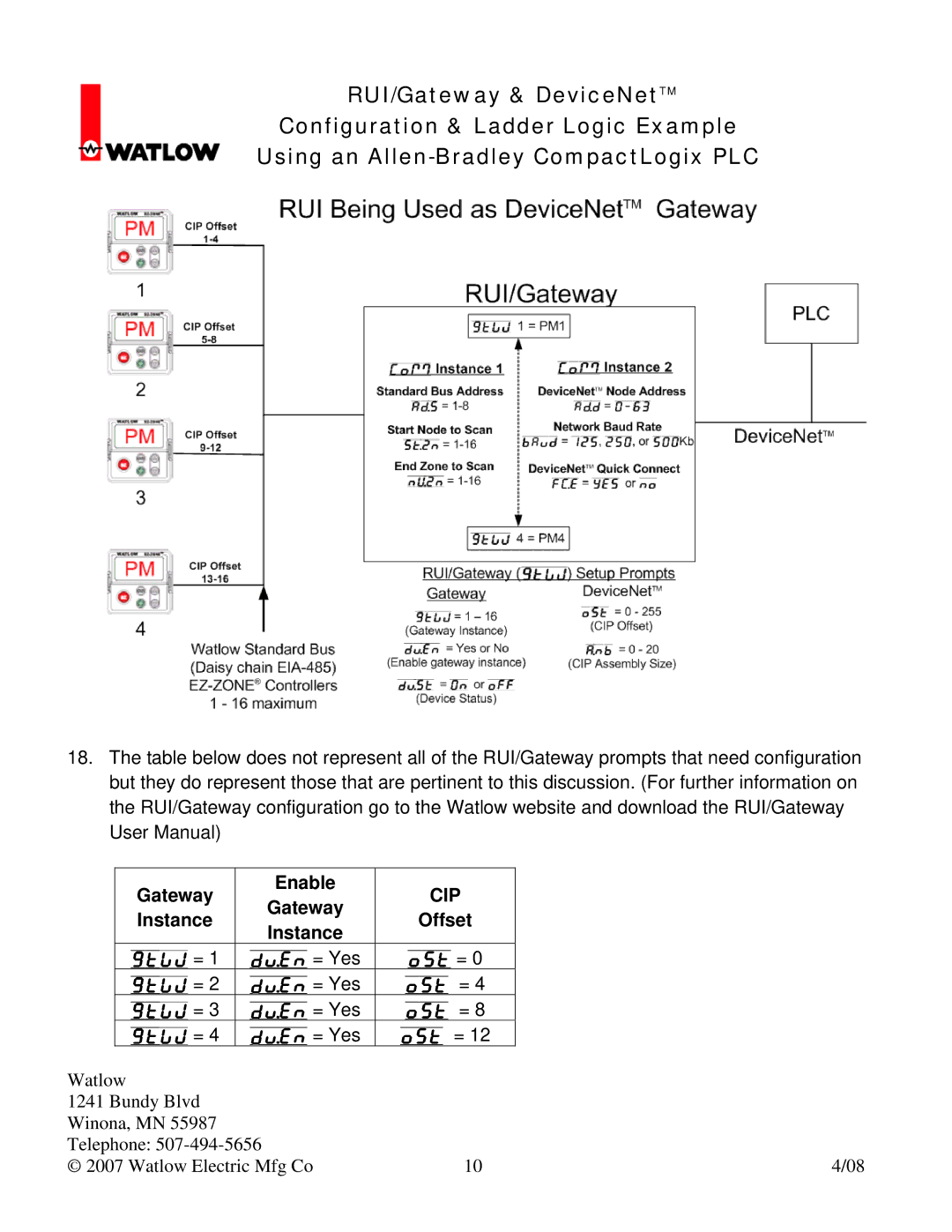
18.The table below does not represent all of the RUI/Gateway prompts that need configuration but they do represent those that are pertinent to this discussion. (For further information on the RUI/Gateway configuration go to the Watlow website and download the RUI/Gateway User Manual)
| Gateway | Enable | CIP |
|
| Gateway |
| ||
| Instance | Offset |
| |
| Instance |
| ||
|
|
|
| |
| Gtw = 1 | Du;en = Yes | ost = 0 |
|
| Gtw = 2 | Du;en = Yes | ost = 4 |
|
| Gtw = 3 | Du;en = Yes | ost = 8 |
|
| Gtw = 4 | Du;en = Yes | ost = 12 |
|
Watlow |
|
|
| |
1241 Bundy Blvd |
|
|
| |
Winona, MN 55987 |
|
|
| |
Telephone: |
|
| ||
© 2007 Watlow Electric Mfg Co | 10 | 4/08 | ||