RUI/Gateway & DeviceNetTM
Configuration & Ladder Logic Example
Using an
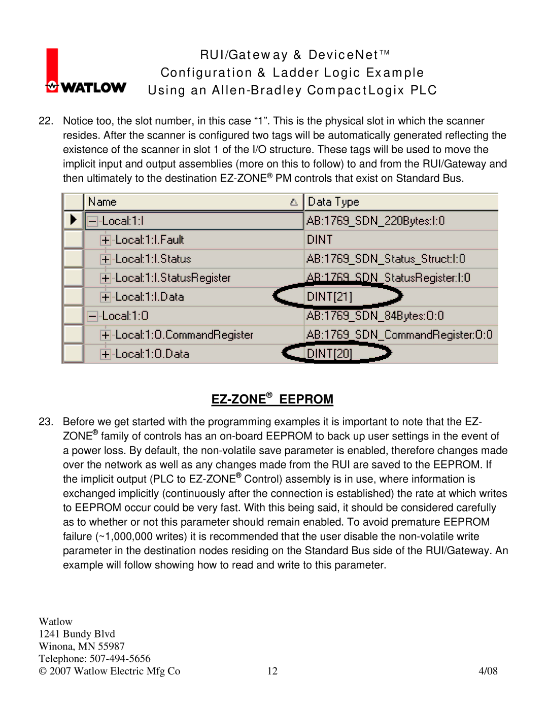
22.Notice too, the slot number, in this case “1”. This is the physical slot in which the scanner resides. After the scanner is configured two tags will be automatically generated reflecting the existence of the scanner in slot 1 of the I/O structure. These tags will be used to move the implicit input and output assemblies (more on this to follow) to and from the RUI/Gateway and then ultimately to the destination
EZ-ZONE® EEPROM
23.Before we get started with the programming examples it is important to note that the EZ- ZONE® family of controls has an
over the network as well as any changes made from the RUI are saved to the EEPROM. If the implicit output (PLC to
Watlow |
|
|
1241 Bundy Blvd |
|
|
Winona, MN 55987 |
|
|
Telephone: |
|
|
© 2007 Watlow Electric Mfg Co | 12 | 4/08 |