Contents
Watlow
RUI/Gateway & Modbus TCP Configuration & Programming Example
Using KEPServerEX Configuring the EZ-ZONE RUI/Gateway
1241 Bundy Blvd
Using KEPServerEX
Configuration & Programming Example
RUI/Gateway & Modbus TCP
Watlow
RUI/Gateway & Modbus TCP Configuration & Programming Example
Using KEPServerEX
1241 Bundy Blvd
Watlow
RUI/Gateway & Modbus TCP Configuration & Programming Example
Using KEPServerEX
1241 Bundy Blvd
Using KEPServerEX
RUI/Gateway & Modbus TCP Configuration & Programming Example
14. Click finish to complete this part of the configuration
Watlow
RUI/Gateway & Modbus TCP Configuration & Programming Example
Using KEPServerEX
1241 Bundy Blvd
Using KEPServerEX
RUI/Gateway & Modbus TCP Configuration & Programming Example
18. Set timing according to your network requirements
Watlow
RUI/Gateway & Modbus TCP Configuration & Programming Example
Using KEPServerEX
1241 Bundy Blvd
Watlow
RUI/Gateway & Modbus TCP Configuration & Programming Example
Using KEPServerEX
1241 Bundy Blvd
Using KEPServerEX
RUI/Gateway & Modbus TCP Configuration & Programming Example
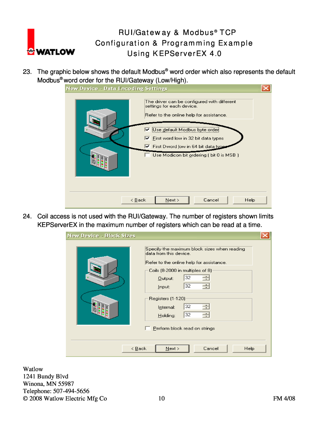
23. The graphic below shows the default Modbus word order which also represents the default Modbus word order for the RUI/Gateway Low/High
Watlow
RUI/Gateway & Modbus TCP Configuration & Programming Example
Using KEPServerEX
1241 Bundy Blvd
Using KEPServerEX
RUI/Gateway & Modbus TCP Configuration & Programming Example
27. This concludes the device RUI/Gateway configuration
Using KEPServerEX
RUI/Gateway & Modbus TCP Configuration & Programming Example
each
Using KEPServerEX
RUI/Gateway & Modbus TCP Configuration & Programming Example
30. To create similar tags for PV2 - PV4 simply click on the duplicate icon circle and change the fields accordingly squares
Using KEPServerEX
RUI/Gateway & Modbus TCP Configuration & Programming Example
said, look closely at the addresses given in defining the CLSP for each of the four PM controls
RUI/Gateway & Modbus TCP Configuration & Programming Example
Using KEPServerEX
Using KEPServerEX
RUI/Gateway & Modbus TCP Configuration & Programming Example
36. In the screen shot that follows one can see the factory defaults for the Assembly Definition Addresses block of 80 words as they are being read through the RUI/Gateway. As explained in the EZ-ZONE PM Communications user manual and above as well, the enumerated values shown in each of these Modbus registers represents the actual Modbus registers for each of the 80 corresponding Assembly Working Addresses. To find what these Modbus registers actually represent as in which parameter is actually defined, check out the Operations & Setup pages of the EZ-ZONE PM Communications user manual
Watlow
RUI/Gateway & Modbus TCP Configuration & Programming Example
Using KEPServerEX
1241 Bundy Blvd
Using KEPServerEX
RUI/Gateway & Modbus TCP Configuration & Programming Example
39. The address shown above represents pointer 12 as shown in the EZ-ZONE PM Communications user manual under the sub-heading of “User Programmable Memory Blocks”
Using KEPServerEX
RUI/Gateway & Modbus TCP Configuration & Programming Example
42. Lastly, in the screen shot below, notice that the 12th pointer has indeed been changed to Idle Set Point circle and the tag created to reflect this arrow shows the current Idle Set Point for PM1. Compare this to the default assembly found in step 37 above