RUI/Gateway & Modbus® TCP
Configuration & Programming Example
Using KEPServerEX 4.0
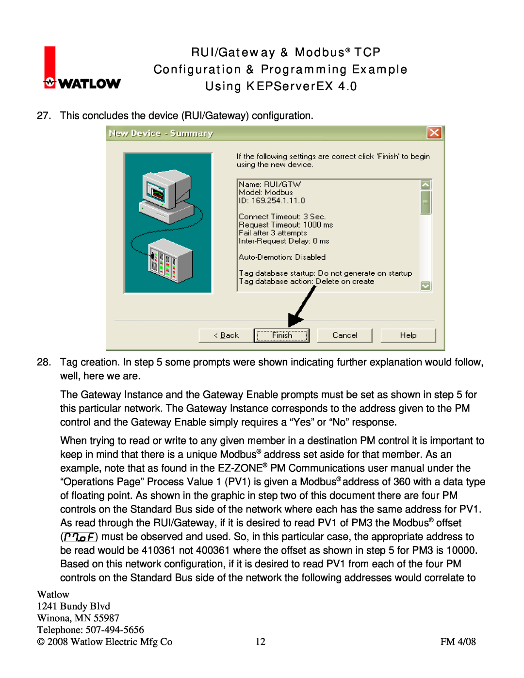
27. This concludes the device (RUI/Gateway) configuration.
28.Tag creation. In step 5 some prompts were shown indicating further explanation would follow, well, here we are.
The Gateway Instance and the Gateway Enable prompts must be set as shown in step 5 for this particular network. The Gateway Instance corresponds to the address given to the PM control and the Gateway Enable simply requires a “Yes” or “No” response.
When trying to read or write to any given member in a destination PM control it is important to keep in mind that there is a unique Modbus® address set aside for that member. As an example, note that as found in the
Watlow |
|
|
1241 Bundy Blvd |
|
|
Winona, MN 55987 |
|
|
Telephone: |
|
|
© 2008 Watlow Electric Mfg Co | 12 | FM 4/08 |