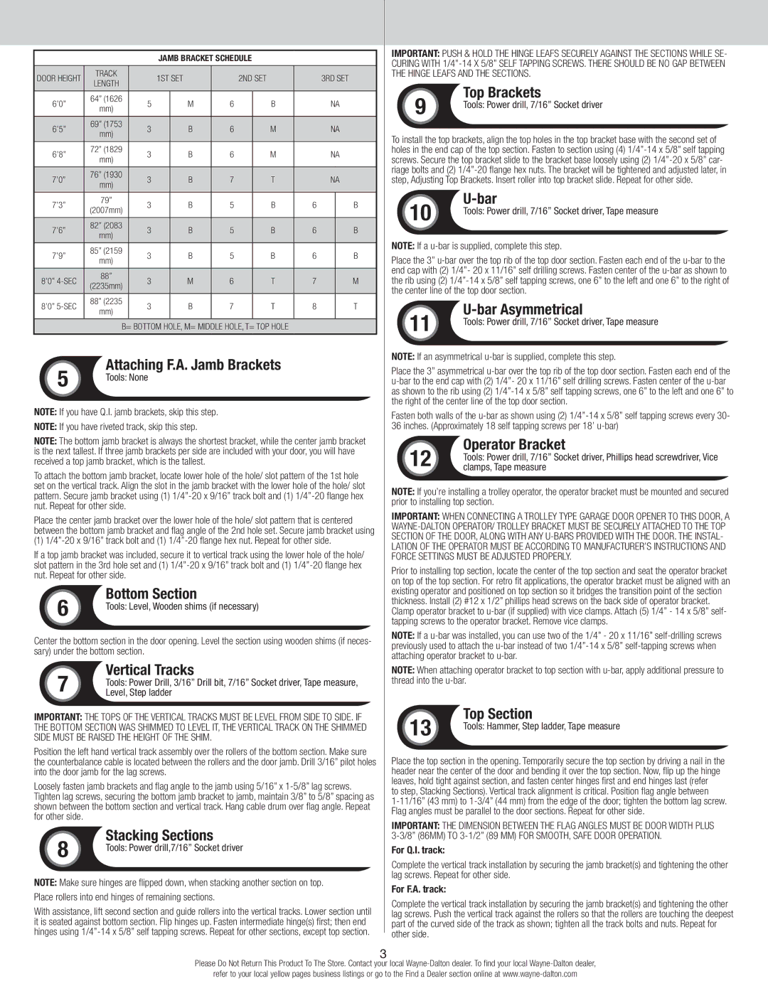
JAMB BRACKET SCHEDULE
DOOR HEIGHT | TRACK | | 1ST SET | | 2ND SET | | 3RD SET |
LENGTH | | | |
| | | | | | | | | |
| | | | | | | | | | |
6’0” | 64” (1626 | 5 | | M | 6 | | B | | NA |
mm) | | | |
| | | | | | | | | |
| | | | | | | | | | |
6’5” | 69” (1753 | 3 | | B | 6 | | M | | NA |
mm) | | | |
| | | | | | | | | |
| | | | | | | | | | |
6’8” | 72” (1829 | 3 | | B | 6 | | M | | NA |
mm) | | | |
| | | | | | | | | |
| | | | | | | | | | |
7’0” | 76” (1930 | 3 | | B | 7 | | T | | NA |
mm) | | | |
| | | | | | | | | |
| | | | | | | | | | |
7’3” | 79” | 3 | | B | 5 | | B | 6 | | B |
(2007mm) | | | |
| | | | | | | | | |
| | | | | | | | | | |
7’6” | 82” (2083 | 3 | | B | 5 | | B | 6 | | B |
mm) | | | |
| | | | | | | | | |
| | | | | | | | | | |
7’9” | 85” (2159 | 3 | | B | 5 | | B | 6 | | B |
mm) | | | |
| | | | | | | | | |
| | | | | | | | | | |
8’0” 4-SEC | 88” | 3 | | M | 6 | | T | 7 | | M |
(2235mm) | | | |
| | | | | | | | | |
| | | | | | | | | | |
8’0” 5-SEC | 88” (2235 | 3 | | B | 7 | | T | 8 | | T |
mm) | | | |
| | | | | | | | | |
| | | | | | | | |
| B= BOTTOM HOLE, M= MIDDLE HOLE, T= TOP HOLE | | | |
| 5 | Attaching F.A. Jamb Brackets |
| Tools: None |
| |
Note: If you have Q.I. jamb brackets, skip this step.
Note: If you have riveted track, skip this step.
Note: The bottom jamb bracket is always the shortest bracket, while the center jamb bracket is the next tallest. If three jamb brackets per side are included with your door, you will have received a top jamb bracket, which is the tallest.
To attach the bottom jamb bracket, locate lower hole of the hole/ slot pattern of the 1st hole set on the vertical track. Align the slot in the jamb bracket with the lower hole of the hole/ slot pattern. Secure jamb bracket using (1) 1/4”-20 x 9/16” track bolt and (1) 1/4”-20 flange hex nut. Repeat for other side.
Place the center jamb bracket over the lower hole of the hole/ slot pattern that is centered between the bottom jamb bracket and flag angle of the 2nd hole set. Secure jamb bracket using
(1) 1/4”-20 x 9/16” track bolt and (1) 1/4”-20 flange hex nut. Repeat for other side.
If a top jamb bracket was included, secure it to vertical track using the lower hole of the hole/ slot pattern in the 3rd hole set and (1) 1/4”-20 x 9/16” track bolt and (1) 1/4”-20 flange hex nut. Repeat for other side.
| 6 | Bottom Section |
| Tools: Level, Wooden shims (if necessary) |
| |
Center the bottom section in the door opening. Level the section using wooden shims (if neces- sary) under the bottom section.
Vertical Tracks
7 Tools: Power Drill, 3/16” Drill bit, 7/16” Socket driver, Tape measure, Level, Step ladder
Important: the tops of the vertical tracks must be level from side to side. If the bottom section was shimmed to level it, the vertical track on the shimmed side must be raised the height of the shim.
Position the left hand vertical track assembly over the rollers of the bottom section. Make sure the counterbalance cable is located between the rollers and the door jamb. Drill 3/16” pilot holes into the door jamb for the lag screws.
Loosely fasten jamb brackets and flag angle to the jamb using 5/16” x 1-5/8” lag screws. Tighten lag screws, securing the bottom jamb bracket to jamb, maintain 3/8” to 5/8” spacing as shown between the bottom section and vertical track. Hang cable drum over flag angle. Repeat for other side.
| 8 | Stacking Sections |
| Tools: Power drill,7/16” Socket driver |
| |
Note: Make sure hinges are flipped down, when stacking another section on top. Place rollers into end hinges of remaining sections.
With assistance, lift second section and guide rollers into the vertical tracks. Lower section until it is seated against bottom section. Flip hinges up. Fasten intermediate hinge(s) first; then end hinges using 1/4”-14 x 5/8” self tapping screws. Repeat for other sections, except top section.
Important: Push & hold the hinge leafs securely against the sections while se- curing with 1/4”-14 x 5/8” self tapping screws. There should be no gap between the hinge leafs and the sections.
| 9 | Top Brackets |
| Tools: Power drill, 7/16” Socket driver |
| |
To install the top brackets, align the top holes in the top bracket base with the second set of holes in the end cap of the top section. Fasten to section using (4) 1/4”-14 x 5/8” self tapping screws. Secure the top bracket slide to the bracket base loosely using (2) 1/4”-20 x 5/8” car- riage bolts and (2) 1/4”-20 flange hex nuts. The bracket will be tightened and adjusted later, in step, Adjusting Top Brackets. Insert roller into top bracket slide. Repeat for other side.
| 10 | U-bar |
| Tools: Power drill, 7/16” Socket driver, Tape measure |
| |
Note: If a u-bar is supplied, complete this step.
Place the 3” u-bar over the top rib of the top door section. Fasten each end of the u-bar to the end cap with (2) 1/4”- 20 x 11/16” self drilling screws. Fasten center of the u-bar as shown to the rib using (2) 1/4”-14 x 5/8” self tapping screws, one 6” to the left and one 6” to the right of the center line of the top door section.
| 11 | U-bar Asymmetrical |
| Tools: Power drill, 7/16” Socket driver, Tape measure |
| |
Note: If an asymmetrical u-bar is supplied, complete this step.
Place the 3” asymmetrical u-bar over the top rib of the top door section. Fasten each end of the u-bar to the end cap with (2) 1/4”- 20 x 11/16” self drilling screws. Fasten center of the u-bar as shown to the rib using (2) 1/4”-14 x 5/8” self tapping screws, one 6” to the left and one 6” to the right of the center line of the top door section.
Fasten both walls of the u-bar as shown using (2) 1/4”-14 x 5/8” self tapping screws every 30- 36 inches. (Approximately 18 self tapping screws per 18’ u-bar)
Operator Bracket
12 Tools: Power drill, 7/16” Socket driver, Phillips head screwdriver, Vice clamps, Tape measure
Note: If you’re installing a trolley operator, the operator bracket must be mounted and secured prior to installing top section.
Important: when connecting a trolley type garage door opener to this door, a Wayne-Dalton operator/ trolley bracket must be securely attached to the top section of the door, along with any u-bars provided with the door. The instal- lation of the operator must be according to manufacturer’s instructions and force settings must be adjusted properly.
Prior to installing top section, locate the center of the top section and seat the operator bracket on top of the top section. For retro fit applications, the operator bracket must be aligned with an existing operator and positioned on top section so it bridges the transition point of the section thickness. Install (2) #12 x 1/2” phillips head screws on the back side of operator bracket. Clamp operator bracket to u-bar (if supplied) with vice clamps. Attach (5) 1/4” - 14 x 5/8” self- tapping screws to the operator bracket. Remove vice clamps.
Note: If a u-bar was installed, you can use two of the 1/4” - 20 x 11/16” self-drilling screws previously used to attach the u-bar instead of two 1/4”-14 x 5/8” self-tapping screws when attaching operator bracket to u-bar.
Note: When attaching operator bracket to top section with u-bar, apply additional pressure to thread into the u-bar.
| 13 | Top Section |
| Tools: Hammer, Step ladder, Tape measure |
| |
Place the top section in the opening. Temporarily secure the top section by driving a nail in the header near the center of the door and bending it over the top section. Now, flip up the hinge leaves, hold tight against section, and fasten center hinges first and end hinges last (refer
to step, Stacking Sections). Vertical track alignment is critical. Position flag angle between
1-11/16” (43 mm) to 1-3/4” (44 mm) from the edge of the door; tighten the bottom lag screw. Flag angles must be parallel to the door sections. Repeat for other side.
Important: the dimension between the flag angles must be door width plus 3-3/8” (86mm) to 3-1/2” (89 mm) for smooth, safe door operation.
For Q.I. track:
Complete the vertical track installation by securing the jamb bracket(s) and tightening the other lag screws. Repeat for other side.
For F.A. track:
Complete the vertical track installation by securing the jamb bracket(s) and tightening the other lag screws. Push the vertical track against the rollers so that the rollers are touching the deepest part of the curved side of the track as shown; tighten all the track bolts and nuts. Repeat for other side.