Arm Assembly
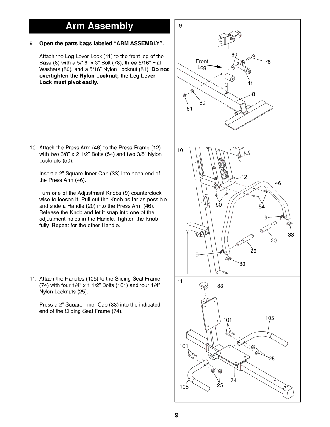
9.Open the parts bags labeled ÒARM ASSEMBLYÓ.
Attach the Leg Lever Lock (11) to the front leg of the Base (8) with a 5/16Ó x 3Ó Bolt (78), three 5/16Ó Flat Washers (80), and a 5/16Ó Nylon Locknut (81). Do not overtighten the Nylon Locknut; the Leg Lever Lock must pivot easily.
10. Attach the Press Arm (46) to the Press Frame (12) |
with two 3/8Ó x 2 1/2Ó Bolts (54) and two 3/8Ó Nylon |
Locknuts (50). |
Insert a 2Ó Square Inner Cap (33) into each end of |
the Press Arm (46). |
Turn one of the Adjustment Knobs (9) counterclock- |
wise to loosen it. Pull out the Knob as far as possible |
and slide a Handle (20) into the Press Arm (46). |
Release the Knob and let it snap into one of the |
9
| 80 |
Front | 78 |
Leg |
|
11
8
![]() 80 81
80 81
10
12
46
5054
adjustment holes in the Handle. Tighten the Knob |
fully. Repeat for the other Handle. |
9
9
33
20
20
11.Attach the Handles (105) to the Sliding Seat Frame (74) with four 1/4Ó x 1 1/2Ó Bolts (101) and four 1/4Ó Nylon Locknuts (25).
Press a 2Ó Square Inner Cap (33) into the indicated end of the Sliding Seat Frame (74).
33
11
33
101105
101
25
74
105 25
9
