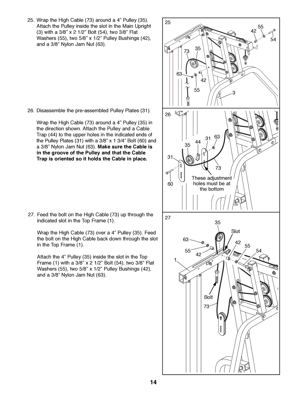
25.Wrap the High Cable (73) around a 4Ó Pulley (35). Attach the Pulley inside the slot in the Main Upright
(3) with a 3/8Ó x 2 1/2Ó Bolt (54), two 3/8Ó Flat Washers (55), two 5/8Ó x 1/2Ó Pulley Bushings (42), and a 3/8Ó Nylon Jam Nut (63).
26.Disassemble the
Wrap the High Cable (73) around a 4Ó Pulley (35) in the direction shown. Attach the Pulley and a Cable Trap (44) to the upper holes in the indicated ends of the Pulley Plates (31) with a 3/8Ó x 1 3/4Ó Bolt (60) and a 3/8Ó Nylon Jam Nut (63). Make sure the Cable is in the groove of the Pulley and that the Cable Trap is oriented so it holds the Cable in place.
27.Feed the bolt on the High Cable (73) up through the indicated slot in the Top Frame (1).
Wrap the High Cable (73) over a 4Ó Pulley (35). Feed the bolt on the High Cable back down through the slot in the Top Frame (1).
Attach the 4Ó Pulley (35) inside the slot in the Top Frame (1) with a 3/8Ó x 2 1/2Ó Bolt (54), two 3/8Ó Flat Washers (55), two 5/8Ó x 1/2Ó Pulley Bushings (42), and a 3/8Ó Nylon Jam Nut (63).
14
25 |
|
| 55 |
|
|
| |
|
|
| 42 |
|
|
| 54 |
73 | 35 |
|
|
|
|
| |
63 |
|
|
|
| 42 |
|
|
| 55 | 3 |
|
|
|
| |
26 |
|
|
|
| 31 | 63 |
|
35 | 44 |
|
|
31 |
|
|
|
|
| 73 |
|
| These adjustment |
| |
60 | holes must be at |
| |
| the bottom |
| |
27 |
| 35 |
|
|
|
| |
|
| Slot |
|
63 |
| 42 |
|
|
| 55 | |
55 | 42 |
| 54 |
1 |
|
| |
|
|
| |
| Bolt |
|
|
| 73 |
|
|
