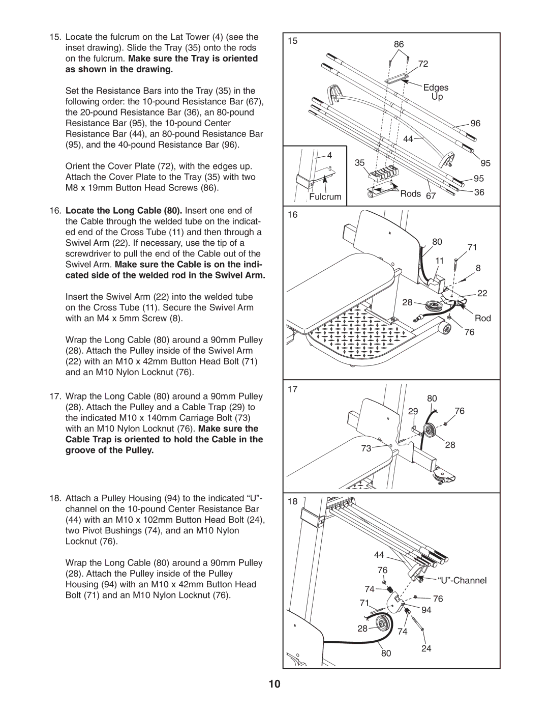
15. Locate the fulcrum on the Lat Tower (4) (see the | 15 |
| 86 |
| |
| inset drawing). Slide the Tray (35) onto the rods |
|
| ||
|
|
|
| ||
|
|
|
|
| |
| on the fulcrum. Make sure the Tray is oriented |
|
| 72 |
|
| as shown in the drawing. |
|
|
| |
|
|
|
|
| |
| Set the Resistance Bars into the Tray (35) in the |
|
| Edges | |
|
|
| Up |
| |
| following order: the |
|
|
| |
|
|
|
|
| |
| the |
|
|
|
|
| Resistance Bar (95), the |
|
|
| 96 |
| Resistance Bar (44), an |
|
| 44 |
|
| (95), and the |
|
|
| |
|
|
|
|
| |
|
| 4 | 35 |
| 95 |
| Orient the Cover Plate (72), with the edges up. |
|
| ||
|
|
|
|
| |
| Attach the Cover Plate to the Tray (35) with two |
|
|
| 95 |
| M8 x 19mm Button Head Screws (86). | Fulcrum |
| Rods 67 | 36 |
|
|
| |||
16. Locate the Long Cable (80). Insert one end of | 16 |
|
|
| |
| the Cable through the welded tube on the indicat- |
|
|
| |
|
|
|
|
| |
| ed end of the Cross Tube (11) and then through a |
|
| 80 |
|
| Swivel Arm (22). If necessary, use the tip of a |
|
| 71 | |
| screwdriver to pull the end of the Cable out of the |
|
|
| |
|
|
| 11 |
| |
| Swivel Arm. Make sure the Cable is on the indi- |
|
| 8 | |
|
|
|
| ||
| cated side of the welded rod in the Swivel Arm. |
|
|
| |
|
|
|
|
| |
| Insert the Swivel Arm (22) into the welded tube |
|
| 28 | 22 |
|
|
|
| ||
| on the Cross Tube (11). Secure the Swivel Arm |
|
|
| |
|
|
|
|
| |
| with an M4 x 5mm Screw (8). |
|
|
| Rod |
| Wrap the Long Cable (80) around a 90mm Pulley |
|
|
| 76 |
|
|
|
|
| |
| (28). Attach the Pulley inside of the Swivel Arm |
|
|
|
|
| (22) with an M10 x 42mm Button Head Bolt (71) |
|
|
|
|
| and an M10 Nylon Locknut (76). |
|
|
|
|
17. Wrap the Long Cable (80) around a 90mm Pulley | 17 |
| 80 |
| |
|
|
| |||
| (28). Attach the Pulley and a Cable Trap (29) to |
|
| 29 | 76 |
| the indicated M10 x 140mm Carriage Bolt (73) |
|
| ||
|
|
|
|
| |
| with an M10 Nylon Locknut (76). Make sure the |
|
|
|
|
| Cable Trap is oriented to hold the Cable in the |
| 73 |
| 28 |
| groove of the Pulley. |
|
| ||
|
|
|
| ||
18. | Attach a Pulley Housing (94) to the indicated “U”- | 18 |
|
|
|
| channel on the |
|
|
| |
|
|
|
|
| |
| (44) with an M10 x 102mm Button Head Bolt (24), |
|
|
|
|
| two Pivot Bushings (74), and an M10 Nylon |
|
|
|
|
| Locknut (76). |
|
|
|
|
| Wrap the Long Cable (80) around a 90mm Pulley |
| 44 |
|
|
|
| 76 |
|
| |
| (28). Attach the Pulley inside of the Pulley |
|
|
| |
|
|
| |||
| Housing (94) with an M10 x 42mm Button Head |
| 74 | ||
|
|
|
| ||
| Bolt (71) and an M10 Nylon Locknut (76). |
| 76 |
| |
|
| 71 |
| ||
|
|
|
| ||
|
|
| 94 |
| |
|
|
|
|
| |
|
|
| 28 | 74 |
|
|
|
|
|
| |
|
|
| 80 | 24 |
|
|
|
|
|
| |
|
| 10 |
|
|
|