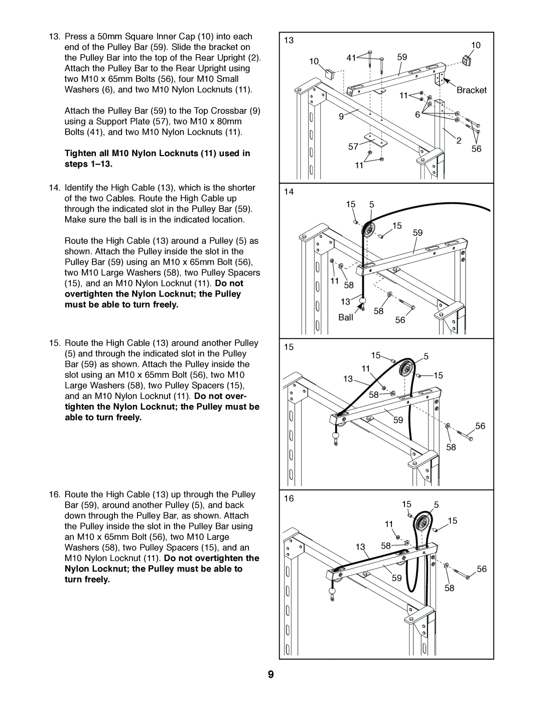
13. Press a 50mm Square Inner Cap (10) into each | 13 |
|
| 10 |
end of the Pulley Bar (59). Slide the bracket on |
|
| ||
|
| 59 | ||
the Pulley Bar into the top of the Rear Upright (2). | 10 | 41 |
| |
Attach the Pulley Bar to the Rear Upright using |
|
|
| |
|
|
|
| |
two M10 x 65mm Bolts (56), four M10 Small |
|
|
|
|
Washers (6), and two M10 Nylon Locknuts (11). |
|
| 11 | Bracket |
|
|
|
| |
Attach the Pulley Bar (59) to the Top Crossbar (9) |
| 9 |
| 6 |
using a Support Plate (57), two M10 x 80mm |
|
| ||
|
|
|
| |
Bolts (41), and two M10 Nylon Locknuts (11). |
|
|
| 2 |
|
| 57 |
| |
Tighten all M10 Nylon Locknuts (11) used in |
|
| 56 | |
|
|
|
| |
steps |
| 11 |
|
|
14. Identify the High Cable (13), which is the shorter | 14 |
|
|
|
of the two Cables. Route the High Cable up |
|
|
| |
| 15 | 5 |
| |
through the indicated slot in the Pulley Bar (59). |
|
| ||
|
|
|
| |
Make sure the ball is in the indicated location. |
|
| 15 |
|
|
|
| 59 | |
Route the High Cable (13) around a Pulley (5) as |
|
|
| |
|
|
|
| |
shown. Attach the Pulley inside the slot in the |
|
|
|
|
Pulley Bar (59) using an M10 x 65mm Bolt (56), |
|
|
|
|
two M10 Large Washers (58), two Pulley Spacers |
| 11 58 |
|
|
(15), and an M10 Nylon Locknut (11). Do not |
|
|
| |
overtighten the Nylon Locknut; the Pulley |
| 13 |
|
|
must be able to turn freely. |
| 58 |
| |
|
| Ball |
| |
|
| 56 |
| |
15. Route the High Cable (13) around another Pulley | 15 |
|
|
|
(5) and through the indicated slot in the Pulley |
| 15 | 5 | |
|
| |||
Bar (59) as shown. Attach the Pulley inside the |
| 11 |
| |
slot using an M10 x 65mm Bolt (56), two M10 |
| 15 | ||
| 13 |
| ||
Large Washers (58), two Pulley Spacers (15), |
|
|
| |
|
| 58 |
| |
and an M10 Nylon Locknut (11). Do not over- |
|
|
| |
tighten the Nylon Locknut; the Pulley must be |
|
|
|
|
able to turn freely. |
|
| 59 | 56 |
|
|
| ||
|
|
|
| |
|
|
|
| 58 |
16. Route the High Cable (13) up through the Pulley | 16 |
| 15 |
|
Bar (59), around another Pulley (5), and back |
| 5 | ||
|
| |||
down through the Pulley Bar, as shown. Attach |
|
| 11 | 15 |
the Pulley inside the slot in the Pulley Bar using |
|
| ||
|
|
| ||
an M10 x 65mm Bolt (56), two M10 Large |
| 13 | 58 |
|
Washers (58), two Pulley Spacers (15), and an |
|
| ||
M10 Nylon Locknut (11). Do not overtighten the |
|
|
|
|
Nylon Locknut; the Pulley must be able to |
|
| 59 | 56 |
turn freely. |
|
| 58 | |
|
|
|
| |
9