CABLE ASSEMBLY
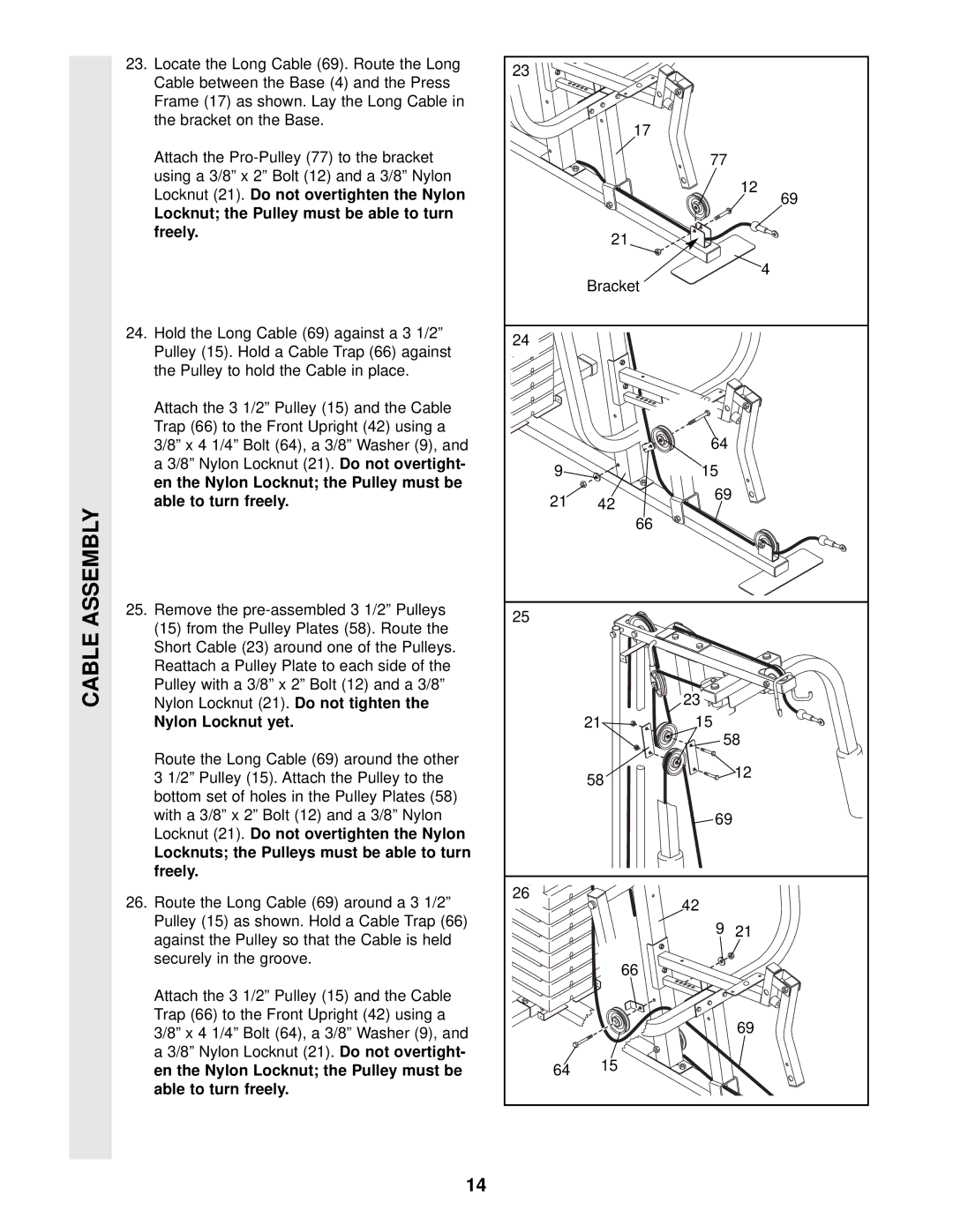
23.Locate the Long Cable (69). Route the Long Cable between the Base (4) and the Press Frame (17) as shown. Lay the Long Cable in the bracket on the Base.
Attach the
Locknut; the Pulley must be able to turn freely.
24.Hold the Long Cable (69) against a 3 1/2” Pulley (15). Hold a Cable Trap (66) against the Pulley to hold the Cable in place.
Attach the 3 1/2” Pulley (15) and the Cable Trap (66) to the Front Upright (42) using a 3/8” x 4 1/4” Bolt (64), a 3/8” Washer (9), and a 3/8” Nylon Locknut (21).Do not overtight- en the Nylon Locknut; the Pulley must be able to turn freely.
25.Remove the
Nylon Locknut yet.
Route the Long Cable (69) around the other 3 1/2” Pulley (15). Attach the Pulley to the bottom set of holes in the Pulley Plates (58) with a 3/8” x 2” Bolt (12) and a 3/8” Nylon Locknut (21). Do not overtighten the Nylon
Locknuts; the Pulleys must be able to turn freely.
26.Route the Long Cable (69) around a 3 1/2” Pulley (15) as shown. Hold a Cable Trap (66) against the Pulley so that the Cable is held securely in the groove.
Attach the 3 1/2” Pulley (15) and the Cable Trap (66) to the Front Upright (42) using a 3/8” x 4 1/4” Bolt (64), a 3/8” Washer (9), and a 3/8” Nylon Locknut (21).Do not overtight- en the Nylon Locknut; the Pulley must be able to turn freely.
23 |
|
|
|
| 17 |
|
|
|
| 77 |
|
|
|
| 12 |
|
|
| 69 |
| 21 |
|
|
| Bracket |
| 4 |
|
|
| |
24 |
|
|
|
|
| 64 |
|
9 |
| 15 |
|
21 | 42 | 69 |
|
|
| ||
| 66 |
|
|
25 |
|
|
|
|
| 23 |
|
| 21 | 15 |
|
|
| 58 | |
| 58 |
| 12 |
|
|
| |
|
| 69 |
|
26 |
| 42 |
|
|
|
| |
|
| 9 | 21 |
| 66 |
|
|
|
|
| 69 |
64 | 15 |
|
|
|
|
| |
14