CABLE ASSEMBLY
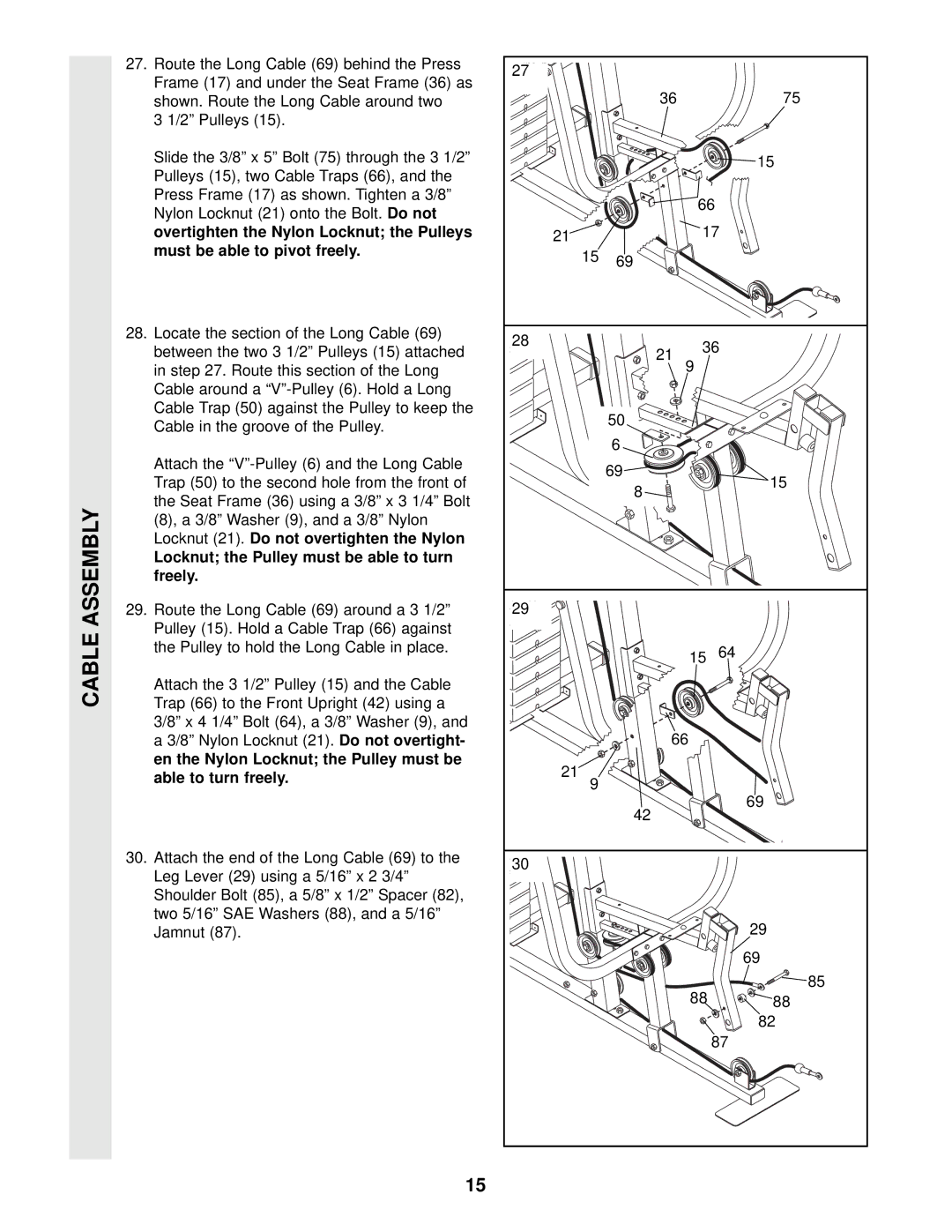
27. Route the Long Cable (69) behind the Press | 27 |
|
|
|
|
Frame (17) and under the Seat Frame (36) as |
|
|
|
| |
|
| 36 |
| 75 | |
shown. Route the Long Cable around two |
|
|
| ||
3 1/2” Pulleys (15). |
|
|
|
|
|
Slide the 3/8” x 5” Bolt (75) through the 3 1/2” |
|
|
|
| 15 |
Pulleys (15), two Cable Traps (66), and the |
|
|
|
| |
|
|
|
|
| |
Press Frame (17) as shown. Tighten a 3/8” |
|
|
| 66 | |
Nylon Locknut (21) onto the Bolt. Do not |
|
|
| ||
|
|
|
|
| |
overtighten the Nylon Locknut; the Pulleys | 21 |
|
| 17 | |
must be able to pivot freely. |
| 15 | 69 |
|
|
|
|
|
| ||
|
|
|
|
| |
28. Locate the section of the Long Cable (69) | 28 |
|
| 36 | |
between the two 3 1/2” Pulleys (15) attached |
| 21 | |||
|
| ||||
|
| 9 |
| ||
in step 27. Route this section of the Long |
|
|
|
| |
Cable around a |
|
|
|
|
|
Cable Trap (50) against the Pulley to keep the |
|
| 50 |
|
|
Cable in the groove of the Pulley. |
|
|
|
| |
|
|
|
|
| |
|
|
| 6 |
|
|
Attach the |
|
| 69 |
|
|
Trap (50) to the second hole from the front of |
|
|
| 15 | |
|
| 8 |
| ||
the Seat Frame (36) using a 3/8” x 3 1/4” Bolt |
|
|
|
| |
|
|
|
|
| |
(8), a 3/8” Washer (9), and a 3/8” Nylon |
|
|
|
|
|
Locknut (21). Do not overtighten the Nylon |
|
|
|
|
|
Locknut; the Pulley must be able to turn |
|
|
|
|
|
freely. |
|
|
|
|
|
29. Route the Long Cable (69) around a 3 1/2” | 29 |
|
|
|
|
Pulley (15). Hold a Cable Trap (66) against |
|
|
|
|
|
the Pulley to hold the Long Cable in place. |
|
|
| 15 | 64 |
|
|
|
| ||
Attach the 3 1/2” Pulley (15) and the Cable |
|
|
|
|
|
Trap (66) to the Front Upright (42) using a |
|
|
|
|
|
3/8” x 4 1/4” Bolt (64), a 3/8” Washer (9), and |
|
| 66 |
| |
a 3/8” Nylon Locknut (21).Do not overtight- |
|
|
| ||
en the Nylon Locknut; the Pulley must be | 21 |
|
|
|
|
able to turn freely. | 9 |
|
|
| |
|
|
|
| ||
|
|
|
| 69 | |
|
|
| 42 |
| |
|
|
|
|
| |
30. Attach the end of the Long Cable (69) to the | 30 |
|
|
|
|
Leg Lever (29) using a 5/16” x 2 3/4” |
|
|
|
| |
|
|
|
|
| |
Shoulder Bolt (85), a 5/8” x 1/2” Spacer (82), |
|
|
|
|
|
two 5/16” SAE Washers (88), and a 5/16” |
|
|
|
| 29 |
Jamnut (87). |
|
|
|
| |
|
|
|
|
| 69 |
|
|
|
| 88 | 85 |
|
|
|
| 88 | |
|
|
|
|
| 82 |
|
|
|
|
| 87 |
15