ATTACHING THE LEG LEVER
To use the Leg Lever (9), first attach the seat to the resistance system (see ADJUSTING THE SEAT on page 13). Then, attach the pulley housings to the low pulley station (see ATTACHING THE PULLEY HOUSINGS on the previous page). Finally, attach the Short Cables (43) to the Leg Lever with two Clips (29).
9 | 43 |
| |
| 29 |
| 29 |
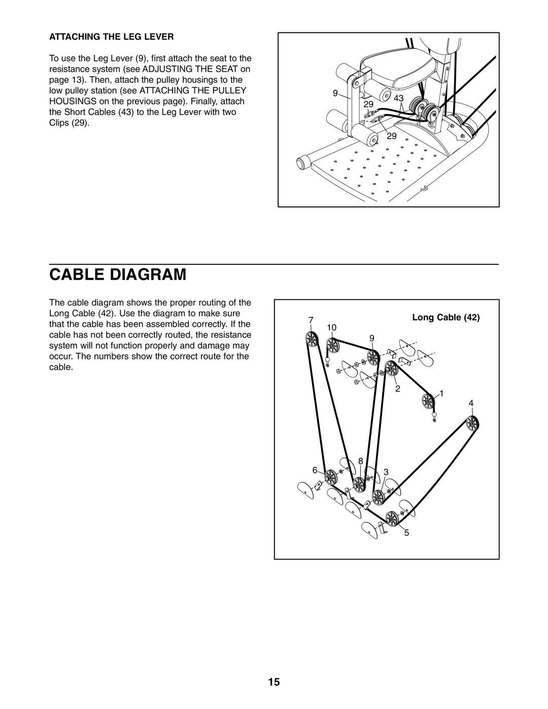
CABLE DIAGRAM
The cable diagram shows the proper routing of the Long Cable (42). Use the diagram to make sure that the cable has been assembled correctly. If the cable has not been correctly routed, the resistance system will not function properly and damage may occur. The numbers show the correct route for the cable.
7 | 10 | Long Cable (42) |
| ||
|
| |
| 9 |
|
| 2 | 1 |
|
| |
|
| 4 |
6 | 8 |
|
3 |
| |
|
| 5 |
15