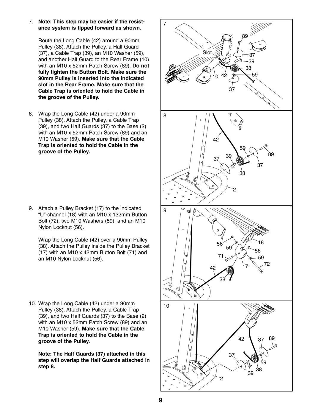
7. | Note: This step may be easier if the resist- | 7 |
|
|
|
|
| ance system is tipped forward as shown. |
|
|
|
| |
|
|
|
|
|
| |
| Route the Long Cable (42) around a 90mm |
|
| 89 |
|
|
|
|
|
|
|
| |
| Pulley (38). Attach the Pulley, a Half Guard | Slot |
|
|
|
|
| (37), a Cable Trap (39), an M10 Washer (59), |
|
| 37 |
| |
| and another Half Guard to the Rear Frame (10) |
|
|
|
| |
|
|
|
| 39 |
| |
| with an M10 x 52mm Patch Screw (89). Do not |
|
|
|
| |
|
|
| 38 |
| ||
| fully tighten the Button Bolt. Make sure the |
|
|
| ||
| 10 42 |
| 59 |
| ||
| 90mm Pulley is inserted into the indicated |
|
| |||
|
|
|
| |||
| slot in the Rear Frame. Make sure that the |
| 37 |
|
|
|
| Cable Trap is oriented to hold the Cable in |
|
|
|
| |
| the groove of the Pulley. |
|
|
|
|
|
8. | Wrap the Long Cable (42) under a 90mm | 8 |
|
|
|
|
| Pulley (38). Attach the Pulley, a Cable Trap |
|
|
|
| |
|
|
|
|
|
| |
| (39), and two Half Guards (37) to the Base (2) |
|
|
|
|
|
| with an M10 x 52mm Patch Screw (89) and an |
|
|
|
|
|
| M10 Washer (59). Make sure that the Cable | 42 |
|
|
|
|
| Trap is oriented to hold the Cable in the |
|
| 59 |
|
|
| groove of the Pulley. |
|
|
|
| |
|
| 39 |
|
| 89 | |
|
| 37 |
|
| ||
|
|
|
|
| ||
|
|
|
|
|
| |
|
|
|
|
| 37 |
|
|
|
|
| 38 |
|
|
|
|
| 2 |
|
|
|
9. | Attach a Pulley Bracket (17) to the indicated | 9 |
|
|
|
|
|
|
|
|
| ||
|
|
|
|
|
| |
| Bolt (72), two M10 Washers (59), and an M10 |
|
|
|
|
|
| Nylon Locknut (56). |
|
|
|
|
|
| Wrap the Long Cable (42) over a 90mm Pulley | 56 |
|
| 18 |
|
| (38). Attach the Pulley inside the Pulley Bracket | 59 |
|
| ||
|
|
| 56 |
| ||
| (17) with an M10 x 42mm Button Bolt (71) and |
|
|
| ||
| 71 |
|
|
| ||
|
|
| 59 |
| ||
| an M10 Nylon Locknut (56). |
|
|
| ||
|
|
|
| 72 | ||
|
| 42 |
| 17 |
| |
|
|
|
|
| ||
|
|
|
|
|
| |
|
| 38 |
|
|
|
|
10. | Wrap the Long Cable (42) under a 90mm | 10 |
|
|
|
|
| Pulley (38). Attach the Pulley, a Cable Trap |
|
|
|
| |
|
|
|
|
|
| |
| (39), and two Half Guards (37) to the Base (2) |
|
|
|
|
|
| with an M10 x 52mm Patch Screw (89) and an |
|
|
|
|
|
| M10 Washer (59). Make sure that the Cable |
|
|
|
|
|
| Trap is oriented to hold the Cable in the |
|
| 42 | 37 | 89 |
| groove of the Pulley. |
|
| |||
|
|
|
|
|
| |
| Note: The Half Guards (37) attached in this |
| 37 |
|
|
|
| step will overlap the Half Guards attached in |
|
|
| 59 | |
| step 8. |
|
|
| ||
|
|
| 39 38 |
| ||
|
| 2 |
|
| ||
|
|
|
|
|
| |
|
| 9 |
|
|
|
|