CABLE ASSEMBLY
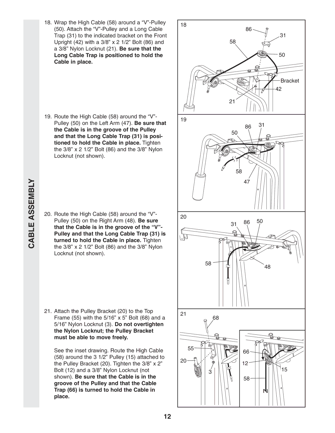
18. Wrap the High Cable (58) around a | 18 |
|
|
|
|
(50). Attach the |
|
| 86 |
| |
|
|
| 31 | ||
Trap (31) to the indicated bracket on the Front |
|
| 58 |
| |
Upright (42) with a 3/8” x 2 1/2” Bolt (86) and |
|
|
|
| |
a 3/8” Nylon Locknut (21). Be sure that the |
|
|
|
| 50 |
Long Cable Trap is positioned to hold the |
|
|
|
| |
Cable in place. |
|
|
|
|
|
|
|
|
|
| Bracket |
|
|
|
|
| 42 |
|
|
| 21 |
|
|
19. Route the High Cable (58) around the “V”- | 19 |
|
|
|
|
Pulley (50) on the Left Arm (47). Be sure that |
|
|
| 31 | |
|
|
| 86 | ||
the Cable is in the groove of the Pulley |
|
|
| ||
|
| 50 |
| ||
|
|
|
| ||
and that the Long Cable Trap (31) is posi- |
|
|
|
| |
|
|
|
|
| |
tioned to hold the Cable in place. Tighten |
|
|
|
|
|
the 3/8” x 2 1/2” Bolt (86) and the 3/8” Nylon |
|
|
|
|
|
Locknut (not shown). |
|
|
|
|
|
|
|
| 58 |
|
|
|
|
|
| 47 |
|
20. Route the High Cable (58) around the “V”- | 20 |
|
|
|
|
Pulley (50) on the Right Arm (48). Be sure |
|
| 86 | 50 | |
|
| 31 | |||
that the Cable is in the groove of the “V”- |
|
|
|
| |
|
|
|
|
| |
Pulley and that the Long Cable Trap (31) is |
|
|
|
|
|
turned to hold the Cable in place. Tighten |
|
|
|
|
|
the 3/8” x 2 1/2” Bolt (86) and the 3/8” Nylon |
|
|
|
|
|
Locknut (not shown). |
|
|
|
|
|
|
|
| 58 |
| 48 |
|
|
|
|
| |
21. Attach the Pulley Bracket (20) to the Top | 21 |
|
|
|
|
Frame (55) with the 5/16” x 5” Bolt (68) and a |
| 68 |
|
| |
|
|
|
| ||
5/16” Nylon Locknut (3). Do not overtighten |
|
|
|
|
|
the Nylon Locknut; the Pulley Bracket |
|
|
|
|
|
must be able to move freely. |
|
|
|
|
|
See the inset drawing. Route the High Cable |
| 55 |
| 66 |
|
|
|
|
| ||
(58) around the 3 1/2” Pulley (15) attached to | 20 |
|
|
|
|
the Pulley Bracket (20). Tighten the 3/8” x 2” |
|
| 12 |
| |
|
|
| 15 | ||
Bolt (12) and a 3/8” Nylon Locknut (not |
|
| 3 |
| |
shown). Be sure that the Cable is in the |
|
|
|
| |
|
|
| 58 |
| |
groove of the Pulley and that the Cable |
|
|
|
| |
|
|
|
|
| |
Trap (66) is turned to hold the Cable in |
|
|
|
|
|
place. |
|
|
|
|
|
12