CABLE ASSEMBLY
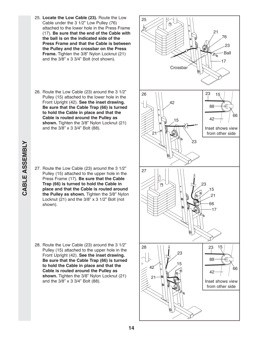
25. Locate the Low Cable (23). Route the Low | 25 |
|
| |
Cable under the 3 1/2” Low Pulley (76) |
|
| ||
|
|
| ||
attached to the lower hole in the Press Frame |
| 21 | ||
(17). Be sure that the end of the Cable with |
| |||
the ball is on the indicated side of the |
|
| 76 | |
|
|
| ||
Press Frame and that the Cable is between |
|
| 23 | |
the Pulley and the crossbar on the Press |
|
| ||
|
| Ball | ||
Frame. Tighten the 3/8” Nylon Locknut (21) |
|
| ||
and the 3/8” x 3 3/4” Bolt (not shown). |
|
| 17 | |
|
|
| ||
| Crossbar |
|
| |
26. Route the Low Cable (23) around the 3 1/2” | 26 | 23 | 15 | |
Pulley (15) attached to the lower hole in the | ||||
|
|
| ||
Front Upright (42). See the inset drawing. | 42 | 88 |
| |
Be sure that the Cable Trap (66) is turned |
|
| ||
to hold the Cable in place and that the |
|
| 66 | |
Cable is routed around the Pulley as | 15 | 42 | ||
| ||||
shown. Tighten the 3/8” Nylon Locknut (21) |
| |||
|
|
| ||
and the 3/8” x 3 3/4” Bolt (88). |
| Inset shows view | ||
| 21 | from other side | ||
|
| 23 |
| |
27. Route the Low Cable (23) around the 3 1/2” | 27 |
|
| |
Pulley (15) attached to the upper hole in the |
|
| ||
|
|
| ||
Press Frame (17). Be sure that the Cable |
|
|
| |
Trap (66) is turned to hold the Cable in |
| 23 |
| |
place and that the Cable is routed around |
| 15 |
| |
the Pulley as shown. Tighten the 3/8” Nylon |
| 21 | ||
Locknut (21) and the 3/8” x 3 1/2” Bolt (not |
| |||
| 66 |
| ||
shown). |
|
| ||
|
| 17 | ||
28. Route the Low Cable (23) around the 3 1/2” | 28 | 23 | 15 | |
Pulley (15) attached to the upper hole in the | ||||
23 |
|
| ||
Front Upright (42). See the inset drawing. |
|
| ||
| 88 |
| ||
Be sure that the Cable Trap (66) is turned | 15 |
| ||
to hold the Cable in place and that the |
|
| ||
42 |
| 66 | ||
Cable is routed around the Pulley as | 42 | |||
|
| |||
shown. Tighten the 3/8” Nylon Locknut (21) |
|
| ||
21 |
|
| ||
and the 3/8” x 3 3/4” Bolt (88). | Inset shows view | |||
| ||||
|
| from other side | ||
14