Mounting the Controller
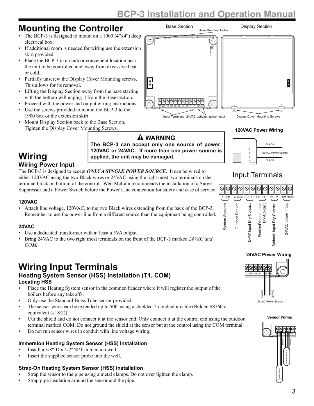
Base Section | Display Section |
Base Mounting Holes
• The
•If additional room is needed for wiring use the extension skirt provided.
•Place the
• Partially unscrew the Display Cover Mounting screws. |
|
|
This allows for its removal. |
|
|
• Lifting the Display Section away from the base starting |
|
|
with the bottom will unplug it from the Base section. |
|
|
• Proceed with the power and output wiring instructions. | T1 COM T2 COM T3+ T3- EXT+ EXT- P+ P- COM 24VAC |
|
• Use the screws provided to mount the |
|
|
1900 box or the extension skirt. | Input Terminals 24VAC optional power input | Display Cover Mounting Screws |
• Mount Display Section back to the Base Section. |
|
|
Tighten the Display Cover Mounting Screws. |
| 120VAC Power Wiring |
|
|
| WARNING |
|
|
|
|
| The |
|
| BLACK |
|
Wiring | 120VAC or 24VAC. If more than one power source is |
|
| 120VAC Power Source | |
applied, the unit may be damaged. |
|
|
|
| |
|
| BLACK | |||
Wiring Power Input
The
either 120VAC using the two Black wires or 24VAC using the right most two terminals on the Input Terminals terminal block on bottom of the control. Weil McLain recommends the installation of a Surge
Suppressor and a Power Switch before the Power Line connection for safety and ease of service. ![]()
![]()
![]()
![]()
![]()
![]()
![]()
![]()
![]()
![]()
T1 COM T2 COM T3+ T3- EXT+ EXT- P+ P- COM 24VAC
120VAC
•Attach line voltage, 120VAC, to the two Black wires extending from the back of the
24VAC
•Use a dedicated transformer with at least a 5VA output.
•Bring 24VAC to the two right most terminals on the front of the
System Sensors { | Outdoor Sensor { | DHW Input | Enable/Disbale Input | Setback Input | 24VAC power Input { |
24VAC Power Wiring
Wiring Input Terminals
Heating System Sensor (HSS) Installation (T1, COM)
Locating HSS
•Place the Heating System sensor in the common header where it will register the output of the boilers before any takeoffs.
•Only use the Standard Brass Tube sensor provided.
•The sensor wires can be extended up to 500' using a shielded
•Cut the shield and do not connect it at the sensor end. Only connect it at the control end using the outdoor terminal marked COM. Do not ground the shield at the sensor but at the control using the COM terminal.
•Do not run sensor wires in conduit with line voltage wiring.
EXT+ EXT- | P+ | P- COM 24VAC |
Comm | 24VAC |
24VAC Power Source
Sensor Wiring
T1 COM | T2 COM T3+ | T |
Immersion Heating System Sensor (HSS) Installation
•Install a 3/8"ID x 1/2"NPT immersion well.
•Insert the supplied sensor probe into the well.
Shield | Shield |
| Outdoor Sensor |
Strap-On Heating System Sensor (HSS) Installation
•Strap the sensor to the pipe using a metal clamps. Do not over tighten the clamp.
•Strap pipe insulation around the sensor and the pipe.
System Temp
3