Output Mode Table
|
| Output 1 | Output 2 | Output 3 |
|
Output Mode | Description | (Yellow | (Blue | (White | Notes |
|
| Wires) | Wires) | Wires) |
|
One On/Off boiler and a System pump | Sys Pump | Boiler | Not used |
| |
One On/Off boiler, a System pump and | Sys Pump | Boiler | DHW |
| |
| a Domestic Hot Water Pump |
|
| Pump |
|
|
|
|
|
| DHW Pump |
Two On/Off boilers and a System pump | Sys Pump | Boiler 1 | Boiler 2 | controlled by DHW | |
|
|
|
|
| Aquastat |
|
|
|
|
| DHW Pump |
One Lo/Hi boiler and a System pump | Sys Pump | Boiler Lo | Boiler Hi | controlled by DHW | |
|
|
|
|
| Aquastat |
|
|
|
|
| Sys Pump controlled |
Three On/Off boilers and NO pumps | Boiler 1 | Boiler 2 | Boiler 3 | using other controls | |
|
|
|
|
| or run constantly. |
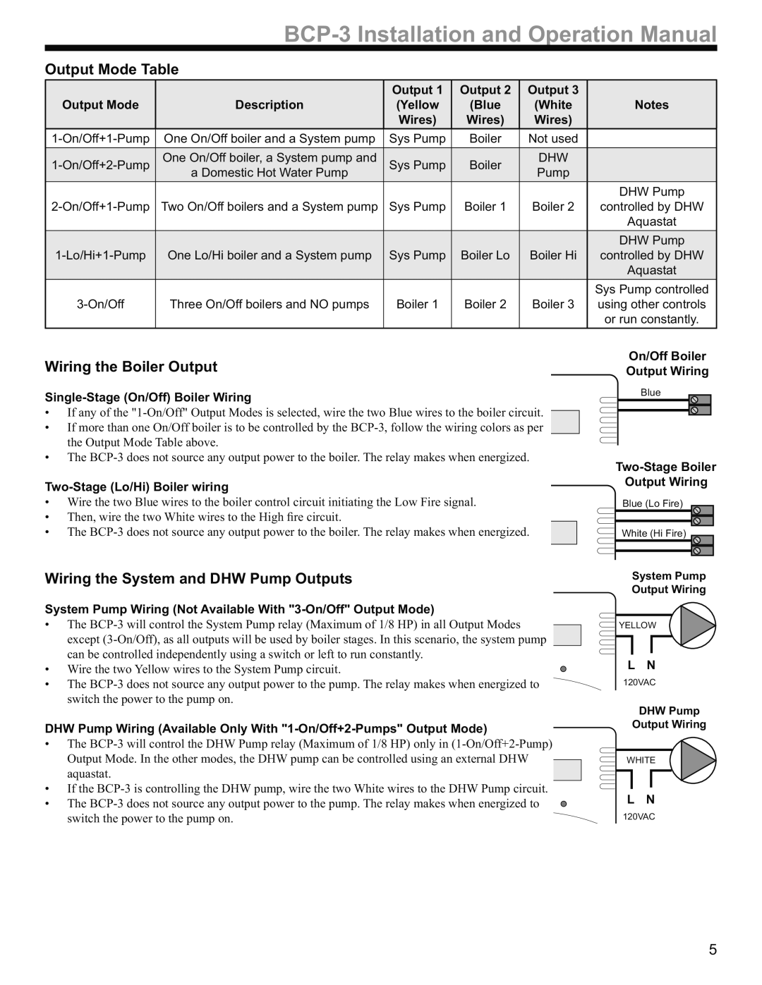
Wiring the Boiler Output
Single-Stage (On/Off) Boiler Wiring
•If any of the
•If more than one On/Off boiler is to be controlled by the
•The
Two-Stage (Lo/Hi) Boiler wiring
•Wire the two Blue wires to the boiler control circuit initiating the Low Fire signal.
•Then, wire the two White wires to the High fire circuit.
• The
On/Off Boiler Output Wiring
Blue
Blue (Lo Fire)
White (Hi Fire)
Wiring the System and DHW Pump Outputs
System Pump Wiring (Not Available With "3-On/Off" Output Mode)
•The
• Wire the two Yellow wires to the System Pump circuit.
• The
DHW Pump Wiring (Available Only With
•The
•If the
• The
System Pump Output Wiring
YELLOW
L N
120VAC
DHW Pump
Output Wiring
WHITE
L N
120VAC
5