GOLD CGi Gas-Fired Water Boiler — Boiler Manual

11a Troubleshooting — procedure

Label all wires prior to disconnection when servicing controls. Wiring errors can cause improper and danger- ous operation.

Never jumper (bypass) rollout thermal fuse element or any other device except for momentary testing as outlined in Troubleshooting Charts. Severe personal injury, death or substantial property damage can re- sult.

Before troubleshooting:

1.Have the following items:

a.Voltmeter that can check 120 VAC and 24 VAC.

b.Microammeter with a minimum scale range of 0-25.

c.Continuity checker.

d.U-tube manometer.

2.Check for 120 VAC (minimum 102 VAC to maximum 132 VAC) to boiler.

3.Make sure thermostat is calling for heat and contacts (including appro- priate zone controls) are closed. Check for 24 VAC between thermostat wire nuts and ground.

Check the following:

1.Wire connectors to control module are se- curely plugged in at module and originating control.

2.Air pressure switch hoses are properly and securely plugged in and are not damaged.

3.Gas pressures:

a.With boiler off — 13” w.c. maximum natural or propane gas pressure up- stream of gas valve.

b.With boiler on:

5” w.c. minimum natural gas pressure or 11” w.c. propane gas pressure upstream of gas valve.

3 ½” w.c. minimum natural gas pressure or 10” w.c. propane gas pressure downstream of gas valve

— Can be adjusted by regulator on gas valve.

11b Troubleshooting — components

Air pressure switch

Make sure boiler water temperature is 100 °F or cooler before starting procedure to obtain appropriate read- ings.

The boiler will not operate correctly unless pressure switch hoses are correctly located. The red hose con- nects from the right side (negative) hose barb to the flue collector. The white hose connects from the left side (positive) hose barb of the switch to the connector box (between flue collector and inducer) as shown in Figure 36, page 49.

Check pressure switch setting

1.See Figure 36, page 49, and Table 9.

2.Remove both air pressure switch hoses from air pressure switch.

3.Install tees and tubing as shown in Figure 36, page 49, to inclined manom- eter.

4.Turn off gas valve and set thermostat to call for heat. Inducer will run but burn- ers will not ignite.

5.Check for 24 VAC between both air pressure switch terminals.

Troubleshooting air pressure reading

1.If manometer reading is lower than the setpoint of the switch (see Table 9)

— check for possible causes:

blockage in hoses

obstruction in inducer housing outlet

loose inducer wheel on motor shaft

inducer motor not in proper rpm

inducer back plate not sealed properly

blockage in block assembly

6.If manometer reading is above the setpoint of the switch (see Table 9), but there is not 24 VAC between both air pressure switch terminals — replace air pressure switch.

Return to normal operation

When pressure reading is correct and air pressure switch is operating properly — remove tees and reinstall hoses to air pressure switch.

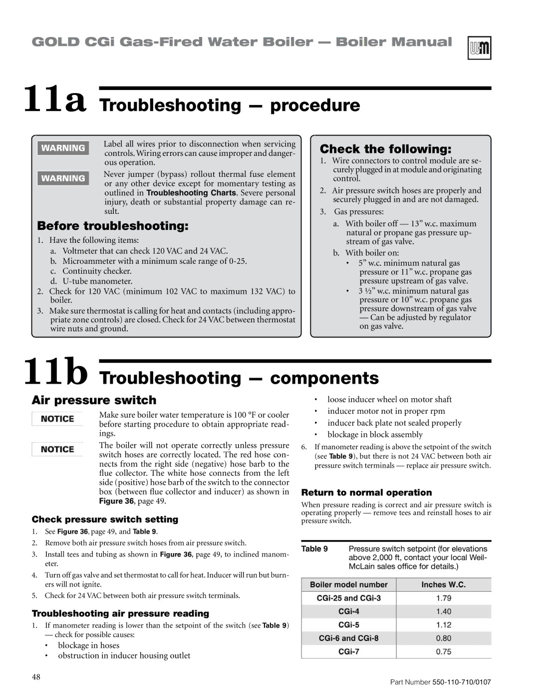
Table 9 Pressure switch setpoint (for elevations above 2,000 ft, contact your local Weil- McLain sales office for details.)

48

Part Number 550-110-710/0107


Page 48
Image 48
Weil-McLain Series 2 manual 11a Troubleshooting procedure, 11b Troubleshooting components, Before troubleshooting

Series 2 specifications

The Weil-McLain Series 2 is a highly regarded boiler system known for its robustness, efficiency, and ease of installation. Designed primarily for residential and light commercial applications, the Series 2 boasts a variety of features that cater to diverse heating needs.

One of the standout characteristics of the Series 2 is its cast iron construction, which provides durability and longevity. Cast iron is well-suited for heat retention, allowing the boiler to operate more efficiently and deliver consistent warmth. The Series 2 is available in multi-fuel options, accommodating both natural gas and propane, making it versatile for various installations.

Efficiency is a key feature of the Weil-McLain Series 2, with annual fuel utilization efficiency (AFUE) ratings that meet or exceed industry standards. This ensures that homeowners can enjoy not only a comfortable living environment but also reduced energy bills. The Series 2 is designed to provide optimal performance, minimizing fuel consumption while maximizing heat output.

Another innovative aspect of the Series 2 is its user-friendly control system. Equipped with advanced controls, the boiler allows for precise temperature management and can easily be integrated with existing heating systems. This adaptability is crucial for ensuring that the boiler matches the specific heating demands of any space, increasing overall comfort levels.

Installation is straightforward, thanks to the boiler's thoughtful design. The Series 2 features a compact footprint, allowing for flexible placement in various settings. Additionally, Weil-McLain provides comprehensive documentation and customer support, making it easier for technicians to install and maintain the system.

The Series 2 also includes features aimed at ease of maintenance. Its clean-out ports facilitate quick access for servicing, ensuring that the boiler remains in peak operating condition throughout its lifespan. Weil-McLain’s commitment to quality means users can expect reliable performance year after year.

Overall, the Weil-McLain Series 2 stands out as an excellent choice for those seeking a dependable, efficient, and straightforward heating solution. Its combination of durable construction, high efficiency, and user-centric design makes it a leading option in the boiler market, appealing to both homeowners and professionals alike. Whether for a new installation or a replacement, the Series 2 is poised to deliver exceptional heating performance.