F. PIVOT BEARING ASSEMBLY
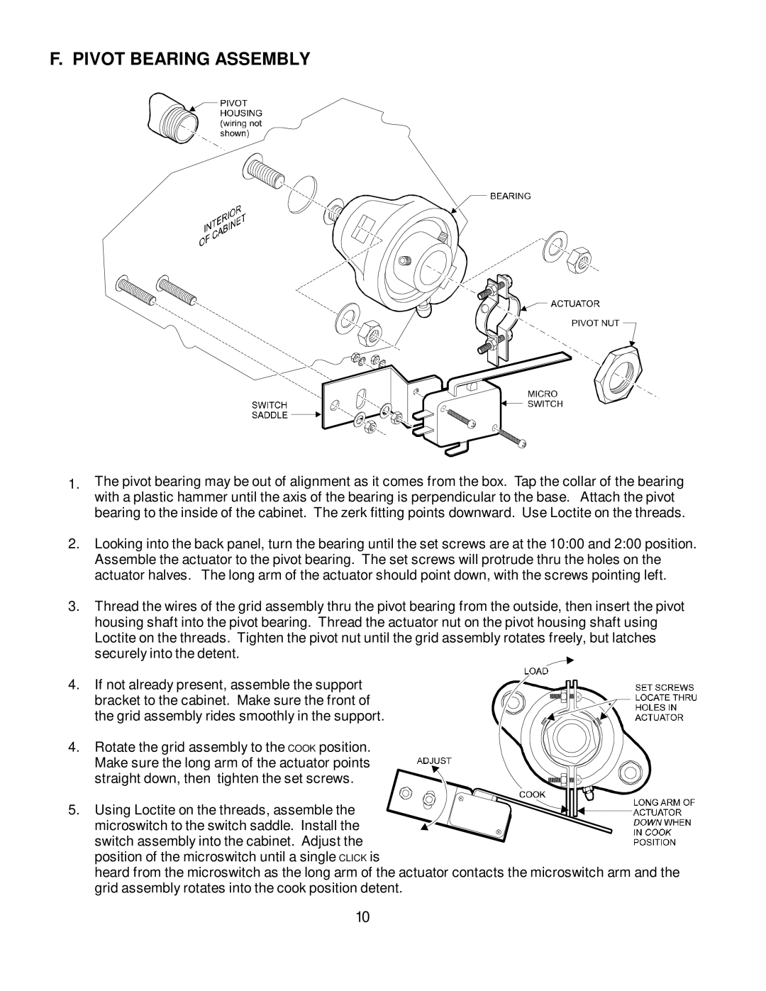
1.The pivot bearing may be out of alignment as it comes from the box. Tap the collar of the bearing with a plastic hammer until the axis of the bearing is perpendicular to the base. Attach the pivot bearing to the inside of the cabinet. The zerk fitting points downward. Use Loctite on the threads.
2.Looking into the back panel, turn the bearing until the set screws are at the 10:00 and 2:00 position. Assemble the actuator to the pivot bearing. The set screws will protrude thru the holes on the actuator halves. The long arm of the actuator should point down, with the screws pointing left.
3.Thread the wires of the grid assembly thru the pivot bearing from the outside, then insert the pivot housing shaft into the pivot bearing. Thread the actuator nut on the pivot housing shaft using Loctite on the threads. Tighten the pivot nut until the grid assembly rotates freely, but latches securely into the detent.
4. If not already present, assemble the support bracket to the cabinet. Make sure the front of the grid assembly rides smoothly in the support.
4. Rotate the grid assembly to the COOK position. Make sure the long arm of the actuator points straight down, then tighten the set screws.
5. Using Loctite on the threads, assemble the microswitch to the switch saddle. Install the
switch assembly into the cabinet. Adjust the position of the microswitch until a single CLICK is
heard from the microswitch as the long arm of the actuator contacts the microswitch arm and the grid assembly rotates into the cook position detent.
10