E.GRID ASSEMBLY
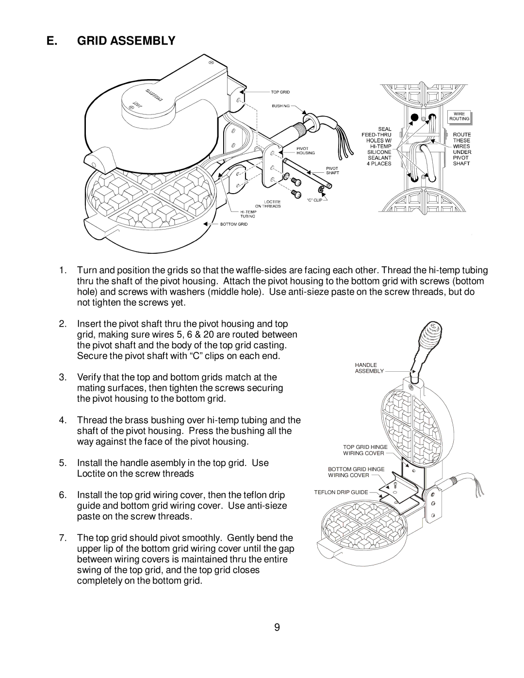
1.Turn and position the grids so that the
2.Insert the pivot shaft thru the pivot housing and top grid, making sure wires 5, 6 & 20 are routed between the pivot shaft and the body of the top grid casting. Secure the pivot shaft with “C”clips on each end.
3.Verify that the top and bottom grids match at the mating surfaces, then tighten the screws securing the pivot housing to the bottom grid.
4.Thread the brass bushing over
5.Install the handle asembly in the top grid. Use Loctite on the screw threads
6.Install the top grid wiring cover, then the teflon drip guide and bottom grid wiring cover. Use
7.The top grid should pivot smoothly. Gently bend the upper lip of the bottom grid wiring cover until the gap between wiring covers is maintained thru the entire swing of the top grid, and the top grid closes completely on the bottom grid.
HANDLE
ASSEMBLY
TOP GRID HINGE
WIRING COVER ![]()
BOTTOM GRID HINGE
WIRING COVER ![]()
TEFLON DRIP GUIDE ![]()
![]()
![]()
![]()
9