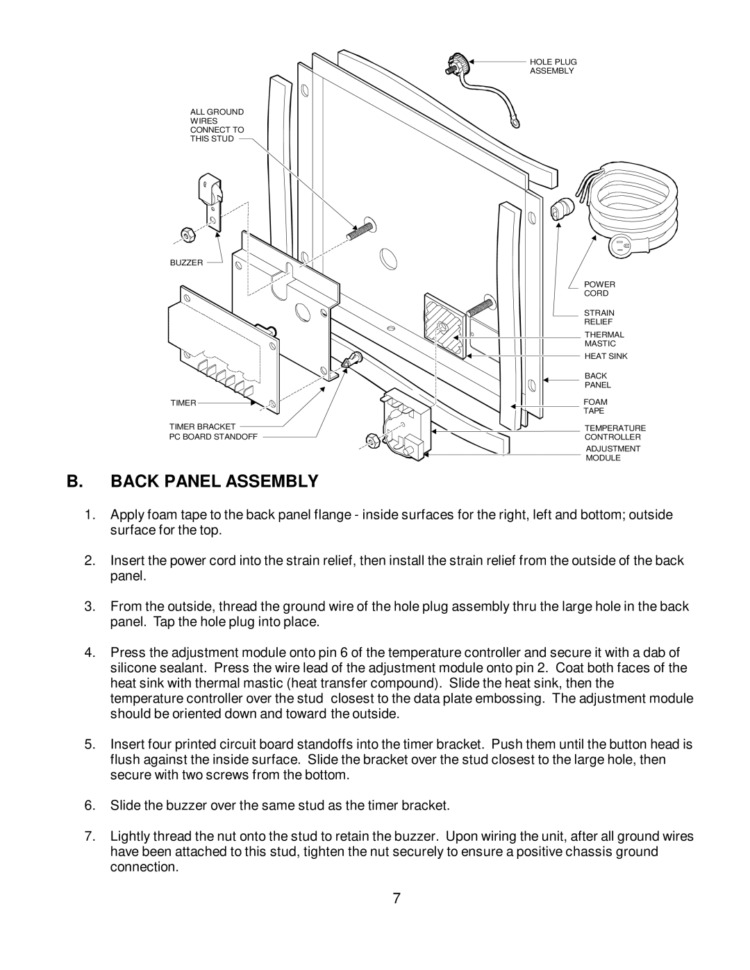
ALL GROUND
WIRES
CONNECT TO
THIS STUD
BUZZER
TIMER
TIMER BRACKET
PC BOARD STANDOFF
B.BACK PANEL ASSEMBLY
HOLE PLUG
ASSEMBLY
POWER
CORD
STRAIN
RELIEF
THERMAL
MASTIC
![]()
![]() HEAT SINK
HEAT SINK
BACK
PANEL
FOAM
TAPE
TEMPERATURE
CONTROLLER
ADJUSTMENT
MODULE
1.Apply foam tape to the back panel flange - inside surfaces for the right, left and bottom; outside surface for the top.
2.Insert the power cord into the strain relief, then install the strain relief from the outside of the back panel.
3.From the outside, thread the ground wire of the hole plug assembly thru the large hole in the back panel. Tap the hole plug into place.
4.Press the adjustment module onto pin 6 of the temperature controller and secure it with a dab of silicone sealant. Press the wire lead of the adjustment module onto pin 2. Coat both faces of the heat sink with thermal mastic (heat transfer compound). Slide the heat sink, then the temperature controller over the stud closest to the data plate embossing. The adjustment module should be oriented down and toward the outside.
5.Insert four printed circuit board standoffs into the timer bracket. Push them until the button head is flush against the inside surface. Slide the bracket over the stud closest to the large hole, then secure with two screws from the bottom.
6.Slide the buzzer over the same stud as the timer bracket.
7.Lightly thread the nut onto the stud to retain the buzzer. Upon wiring the unit, after all ground wires have been attached to this stud, tighten the nut securely to ensure a positive chassis ground connection.
7