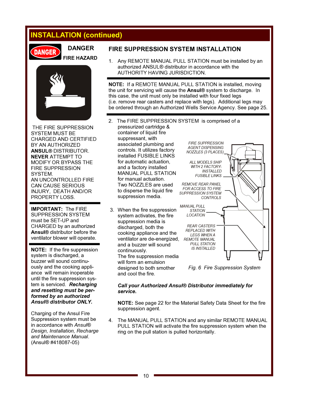
MANUAL PULL STATION LOCATION
FIRE SUPPRESSION AGENT DISPENSING NOZZLES (3 PLACES)
ALL MODELS SHIP
WITH 2 FACTORY- INSTALLED FUSIBLE LINKS
REMOVE REAR PANEL FOR ACCESS TO FIRE SUPPRESSION SYSTEM CONTROLS

INSTALLATION (continued)

DANGER

FIRE HAZARD

THE FIRE SUPPRESSION SYSTEM MUST BE CHARGED AND CERTIFIED BY AN AUTHORIZED ANSUL® DISTRIBUTOR. NEVER ATTEMPT TO MODIFY OR BYPASS THE FIRE SUPPRESSION SYSTEM.

AN UNCONTROLLED FIRE CAN CAUSE SERIOUS INJURY, DEATH AND/OR PROPERTY LOSS.

FIRE SUPPRESSION SYSTEM INSTALLATION

1.Any REMOTE MANUAL PULL STATION must be installed by an authorized ANSUL® distributor in accordance with the

AUTHORITY HAVING JURISDICTION.

NOTE: If a REMOTE MANUAL PULL STATION is installed, moving the unit for servicing will cause the Ansul® system to discharge. In this case, the unit must only be installed with four fixed legs

(i.e. remove rear casters and replace with legs). Additional legs may be ordered through an Authorized Wells Service Agency. See page 25.

2.The FIRE SUPPRESSION SYSTEM is comprised of a pressurized cartridge &

container of liquid fire

suppressant, with associated plumbing and controls. It utilizes factory installed FUSIBLE LINKS for automatic actuation, and a factory installed

MANUAL PULL STATION for manual actuation. Two NOZZLES are used to disperse the liquid fire suppression media.

IMPORTANT: The FIRE SUPPRESSION SYSTEM must be SET-UP and CHARGED by an authorized Ansul® distributor before the ventilator blower will operate.

NOTE: If the fire suppression system is discharged, a buzzer will sound continu- ously and the cooking appli- ance will remain inoperable until the fire suppression sys-

3.When the fire suppression system activates, the fire suppression media is discharged, both the cooking appliance and the ventilator are de-energized, and a buzzer will sound continuously.

The fire suppression media will form an emulsion designed to both smother and cool the fire.

REAR CASTERS

REPLACED WITH

LEGS WHEN A

REMOTE MANUAL

PULL STATION

IS INSTALLED

Fig. 6 Fire Suppression System

tem is serviced. Recharging and resetting must be per- formed by an authorized Ansul® distributor ONLY.

Charging of the Ansul Fire Suppression system must be in accordance with Ansul® Design, Installation, Recharge and Maintenance Manual. (Ansul® #418087-05)

Call your Authorized Ansul® Distributor immediately for service.

NOTE: See page 22 for the Material Safety Data Sheet for the fire suppression agent.

4.The MANUAL PULL STATION and any similar REMOTE MANUAL PULL STATION will activate the fire suppression system when the ring on the pull station is pulled horizontally.

10

Page 12
Image 12
Wells WV-4HSRW operation manual Fire Suppression System Installation, Fire Hazard, Authority Having Jurisdiction

WV-4HSRW specifications

The Wells WV-4HSRW is a robust and versatile water well drilling rig designed for both the professional driller and the demanding environmental conditions often encountered in well drilling projects. This machine is particularly celebrated for its efficiency, ease of use, and the advanced technologies integrated into its design.

One of the standout features of the WV-4HSRW is its powerful hydraulic system. The rig utilizes a high-pressure hydraulic pump that delivers optimal performance, allowing for effective drilling in various soil conditions. The rig's hydraulic capabilities enable efficient rotary drilling and can accommodate a wide variety of drill bits, making it adaptable to different geological formations.

The WV-4HSRW is equipped with a 4-wheel drive system, which is crucial for maneuverability in rugged and uneven terrains. This feature ensures that the rig remains stable and can move seamlessly from one site to another, even in challenging conditions. Additionally, the rig's compact design enhances its ability to navigate tight spaces, which is often a necessity for residential and urban drilling projects.

Safety and operator comfort are paramount in the design of the Wells WV-4HSRW. The rig features an ergonomic cab that provides excellent visibility and protection for the operator. Moreover, the controls are intuitively laid out, which simplifies operation for both experienced drillers and those new to the field. The inclusion of safety features, such as emergency stop systems and reinforced structures, further enhances the safety profile of the rig.

In terms of power, the WV-4HSRW is often powered by efficient diesel engines that provide the necessary energy while remaining fuel-efficient. This not only reduces operational costs but also minimizes the environmental footprint, aligning with modern sustainability goals. The machine’s design allows for easy maintenance access, ensuring that routine checks and repairs can be carried out with minimal downtime.

Overall, the Wells WV-4HSRW represents a significant advancement in drilling technology, combining robust construction with innovative hydraulic systems, user-friendly controls, and enhanced safety features. Whether for water well drilling, geothermal projects, or environmental investigations, this rig is engineered to deliver reliability and effectiveness in every project it undertakes. Its blend of performance and versatility makes it an invaluable asset to any drilling operation.