INSTALLATION (continued)
FILTERS INSTALLATION
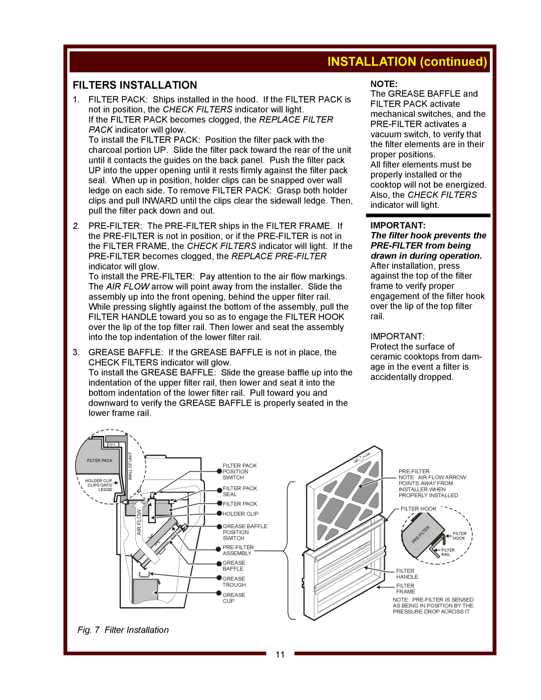
1.FILTER PACK: Ships installed in the hood. If the FILTER PACK is not in position, the CHECK FILTERS indicator will light.
If the FILTER PACK becomes clogged, the REPLACE FILTER PACK indicator will glow.
To install the FILTER PACK: Position the filter pack with the charcoal portion UP. Slide the filter pack toward the rear of the unit until it contacts the guides on the back panel. Push the filter pack UP into the upper opening until it rests firmly against the filter pack seal. When up in position, holder clips can be snapped over wall ledge on each side. To remove FILTER PACK: Grasp both holder clips and pull INWARD until the clips clear the sidewall ledge. Then, pull the filter pack down and out.
2.
To install the
While pressing slightly against the bottom of the assembly, pull the FILTER HANDLE toward you so as to engage the FILTER HOOK over the lip of the top filter rail. Then lower and seat the assembly into the top indentation of the lower filter rail.
3.GREASE BAFFLE: If the GREASE BAFFLE is not in place, the CHECK FILTERS indicator will glow.
To install the GREASE BAFFLE: Slide the grease baffle up into the indentation of the upper filter rail, then lower and seat it into the bottom indentation of the lower filter rail. Pull toward you and downward to verify the GREASE BAFFLE is properly seated in the lower frame rail.
NOTE:
The GREASE BAFFLE and FILTER PACK activate mechanical switches, and the
All filter elements must be properly installed or the cooktop will not be energized. Also, the CHECK FILTERS indicator will light.
IMPORTANT:
The filter hook prevents the
IMPORTANT: Protect the surface of ceramic cooktops from dam- age in the event a filter is accidentally dropped.
SEAL
FILTER PACK
HOLDER CLIP CLIPS ONTO LEDGE
OFUNIT | FILTER PACK | |
WALL | POSITION | |
SWITCH | ||
| FILTER PACK | |
| SEAL | |
FLOW | FILTER PACK | |
HOLDER CLIP | ||
| ||
AIR | GREASE BAFFLE | |
POSITION | ||
| SWITCH | |
| ||
| ASSEMBLY | |
| GREASE | |
| BAFFLE | |
| GREASE | |
| TROUGH | |
| GREASE | |
| CUP |
![]() NOTE: AIR FLOW ARROW
NOTE: AIR FLOW ARROW
POINTS AWAY FROM INSTALLER WHEN PROPERLY INSTALLED
FILTER HOOK ![]()
![]()
![]()
|
| R |
|
|
| E |
|
| |
T |
|
| FILTER | |
IL |
|
|
| |
|
|
| HOOK | |
E |
|
|
| |
R |
|
|
|
|
P |
|
|
|
|
![]() FILTER
FILTER
RAIL
![]()
![]() FILTER HANDLE
FILTER HANDLE
![]() FILTER FRAME
FILTER FRAME
NOTE:
AS BEING IN POSITION BY THE
PRESSURE DROP ACROSS IT.
Fig. 7 Filter Installation
11