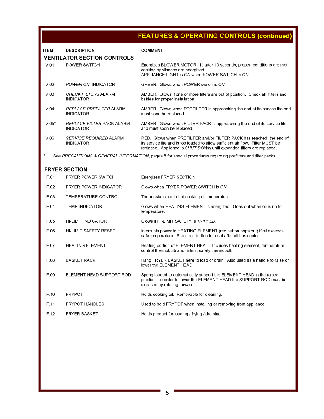
WV-FGRW specifications
Wells WV-FGRW is a prominent and innovative water treatment solution designed to meet the evolving demands of water quality and conservation. This state-of-the-art facility is a paradigm of modern engineering, leveraging advanced technologies to ensure that residents and industries alike receive clean, safe, and reliable water supply.One of the standout features of Wells WV-FGRW is its use of cutting-edge filtration systems. These systems employ multiple stages of filtration, including sand, activated carbon, and membrane filtration, to effectively remove contaminants such as sediments, chemicals, and biological pathogens. This multi-barrier approach not only enhances water purity but also improves the overall taste and odor of the water.
Additionally, the facility integrates real-time monitoring technologies, utilizing sensors and automated data analysis to track water quality parameters continuously. This enables the staff to respond promptly to any fluctuations in water quality, ensuring a swift resolution to potential issues. Such proactive management significantly reduces the risks linked to waterborne diseases and maintains regulatory compliance.
Wells WV-FGRW is also designed with sustainability in mind. Energy-efficient technologies power the treatment processes, minimizing the ecological footprint. Solar panels and other renewable energy sources contribute to a significant portion of the operational energy needs, demonstrating a commitment to environmental stewardship.
Furthermore, the facility employs an advanced chemical dosing system to effectively manage disinfection processes. Utilizing technologies like ultraviolet (UV) light and ozone treatment, the facility achieves an efficient, non-toxic method of disinfecting water, reducing reliance on harsh chemicals.
Another key characteristic of Wells WV-FGRW is its commitment to community involvement and education. The facility frequently conducts workshops and tours for local schools and organizations to raise awareness about water conservation and the importance of maintaining clean water sources.
In conclusion, Wells WV-FGRW exemplifies excellence in water treatment, showcasing an array of modern technologies and a firm dedication to sustainability and community engagement. With its innovative approach to managing water resources, the facility stands as a vital asset for the local community, ensuring a safe and reliable water supply for generations to come.

