ASSEMBLY
Assembly requires two persons. Set the treadmill in a cleared area and remove all packing materials. Do not dispose of the packing materials until assembly is completed. Note: The underside of the treadmill walking belt is coated with
Assembly requires the included hex keys![]() and your own phillips screwdriver
and your own phillips screwdriver ![]()
![]() , wire
, wire
cutters ![]() , and needlenose pliers
, and needlenose pliers ![]() .
.
For help identifying the assembly hardware, see the PART IDENTIFICATION CHART in the centre of this manual. Note: The assembly hardware and other small parts are packaged in separate part bags. Do not open the part bags until instructed to do so.
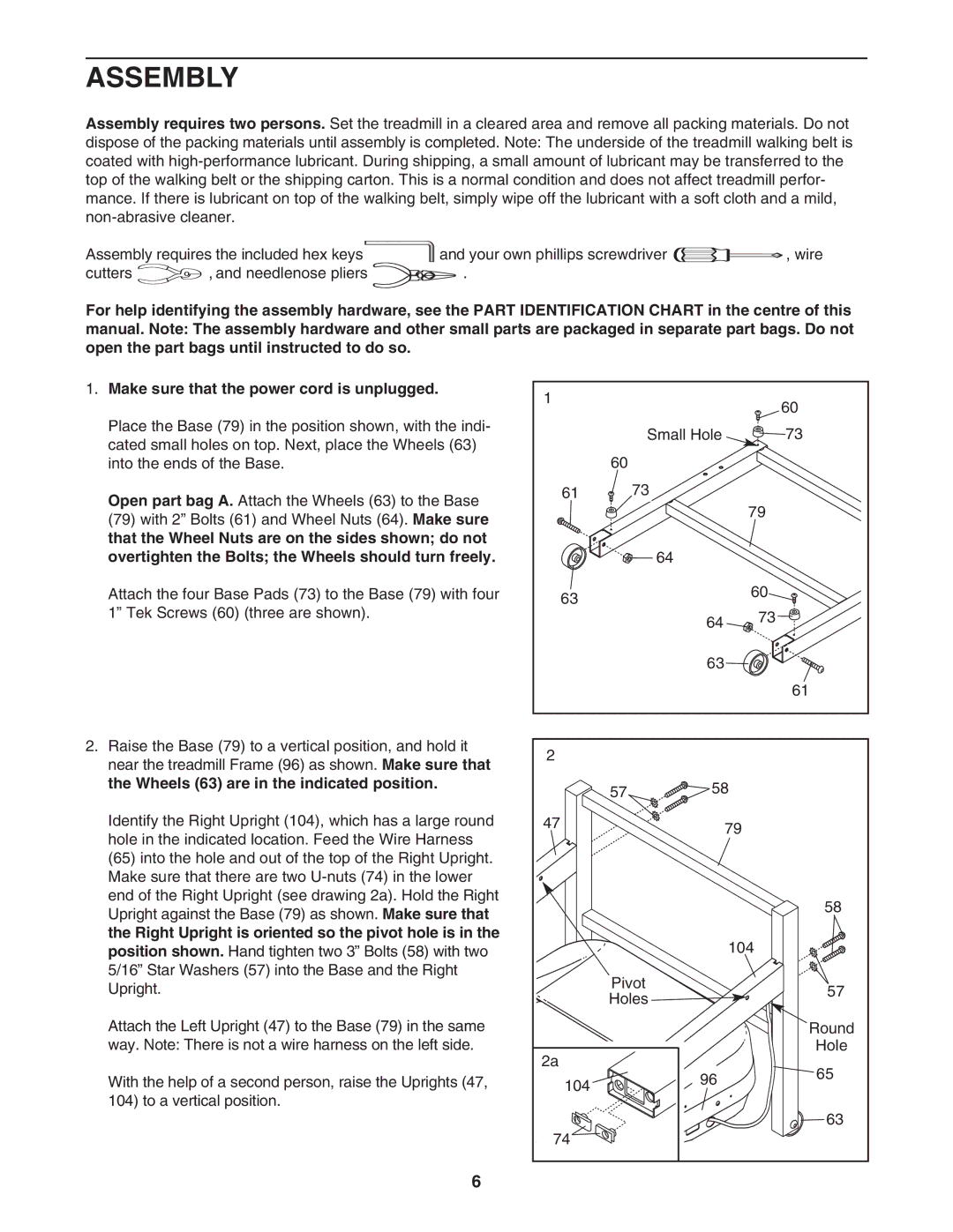
1. Make sure that the power cord is unplugged. | 1 |
|
|
|
|
|
| 60 | |
|
|
|
| |
Place the Base (79) in the position shown, with the indi- |
| Small Hole |
| 73 |
cated small holes on top. Next, place the Wheels (63) |
|
| ||
|
|
|
| |
into the ends of the Base. | 60 |
|
|
|
Open part bag A. Attach the Wheels (63) to the Base | 61 | 73 |
|
|
|
| 79 |
| |
(79) with 2” Bolts (61) and Wheel Nuts (64). Make sure |
|
|
| |
|
|
|
| |
that the Wheel Nuts are on the sides shown; do not |
|
|
|
|
overtighten the Bolts; the Wheels should turn freely. |
| 64 |
|
|
Attach the four Base Pads (73) to the Base (79) with four | 63 |
| 60 |
|
1” Tek Screws (60) (three are shown). |
| 73 |
| |
| 64 |
| ||
|
|
|
| |
|
| 63 |
|
|
|
|
|
| 61 |
2. Raise the Base (79) to a vertical position, and hold it | 2 |
|
|
|
near the treadmill Frame (96) as shown. Make sure that |
|
|
| |
|
|
|
| |
the Wheels (63) are in the indicated position. | 57 | 58 |
| |
|
| |||
Identify the Right Upright (104), which has a large round | 47 |
| 79 |
|
hole in the indicated location. Feed the Wire Harness |
|
|
| |
|
|
|
| |
(65) into the hole and out of the top of the Right Upright. |
|
|
|
|
Make sure that there are two |
|
|
|
|
end of the Right Upright (see drawing 2a). Hold the Right |
|
|
| 58 |
Upright against the Base (79) as shown. Make sure that |
|
|
| |
|
|
|
| |
the Right Upright is oriented so the pivot hole is in the |
|
| 104 |
|
position shown. Hand tighten two 3” Bolts (58) with two |
|
|
| |
5/16” Star Washers (57) into the Base and the Right | Pivot |
|
| |
Upright. |
| 57 | ||
Holes |
| |||
|
|
| ||
Attach the Left Upright (47) to the Base (79) in the same |
|
|
| Round |
way. Note: There is not a wire harness on the left side. | 2a |
|
| Hole |
|
|
| 65 | |
With the help of a second person, raise the Uprights (47, | 104 | 96 |
| |
|
| |||
104) to a vertical position. |
|
|
|
|
|
|
|
| 63 |
| 74 |
|
|
|
6