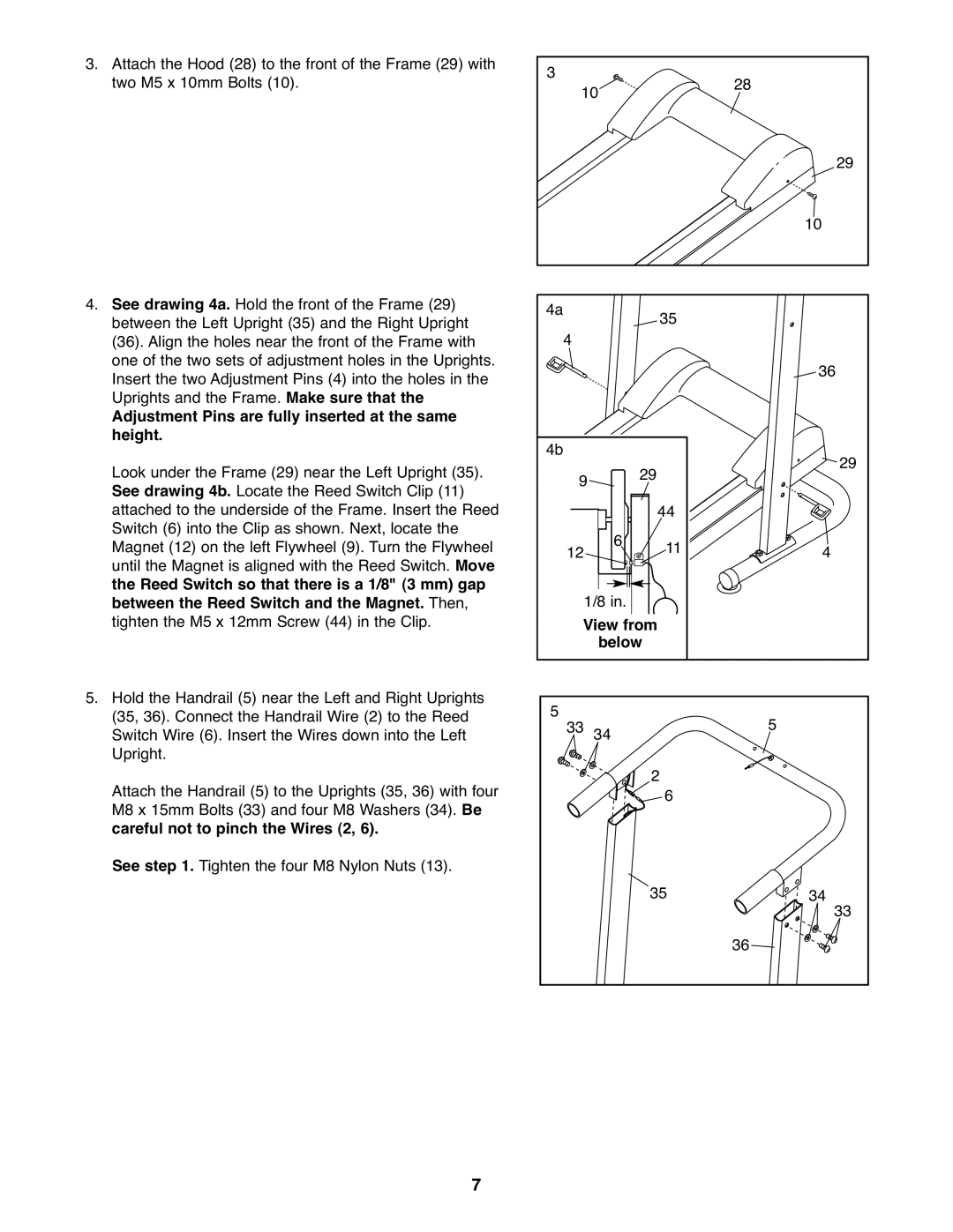
3.Attach the Hood (28) to the front of the Frame (29) with two M5 x 10mm Bolts (10).
4.See drawing 4a. Hold the front of the Frame (29) between the Left Upright (35) and the Right Upright
(36). Align the holes near the front of the Frame with one of the two sets of adjustment holes in the Uprights. Insert the two Adjustment Pins (4) into the holes in the Uprights and the Frame. Make sure that the
Adjustment Pins are fully inserted at the same height.
Look under the Frame (29) near the Left Upright (35). See drawing 4b. Locate the Reed Switch Clip (11) attached to the underside of the Frame. Insert the Reed Switch (6) into the Clip as shown. Next, locate the Magnet (12) on the left Flywheel (9). Turn the Flywheel until the Magnet is aligned with the Reed Switch. Move the Reed Switch so that there is a 1/8" (3 mm) gap between the Reed Switch and the Magnet. Then, tighten the M5 x 12mm Screw (44) in the Clip.
5.Hold the Handrail (5) near the Left and Right Uprights (35, 36). Connect the Handrail Wire (2) to the Reed Switch Wire (6). Insert the Wires down into the Left Upright.
Attach the Handrail (5) to the Uprights (35, 36) with four M8 x 15mm Bolts (33) and four M8 Washers (34). Be careful not to pinch the Wires (2, 6).
See step 1. Tighten the four M8 Nylon Nuts (13).
3 | 10 |
|
| 28 |
|
|
|
| 29 |
|
|
|
| 10 |
4a | 4 |
| 35 |
|
|
|
| 36 | |
|
|
|
| |
4b | 9 | 29 | 44 | 29 |
|
| 6 |
| |
| 12 | 11 | 4 | |
| 1/8 in. |
|
| |
| View from |
|
| |
| below |
|
| |
5 33 | 34 | 5 |
|
| 2 6 |
|
|
| 35 | 34 | 33 |
|
| 36 |
|
7