2.Unit Description
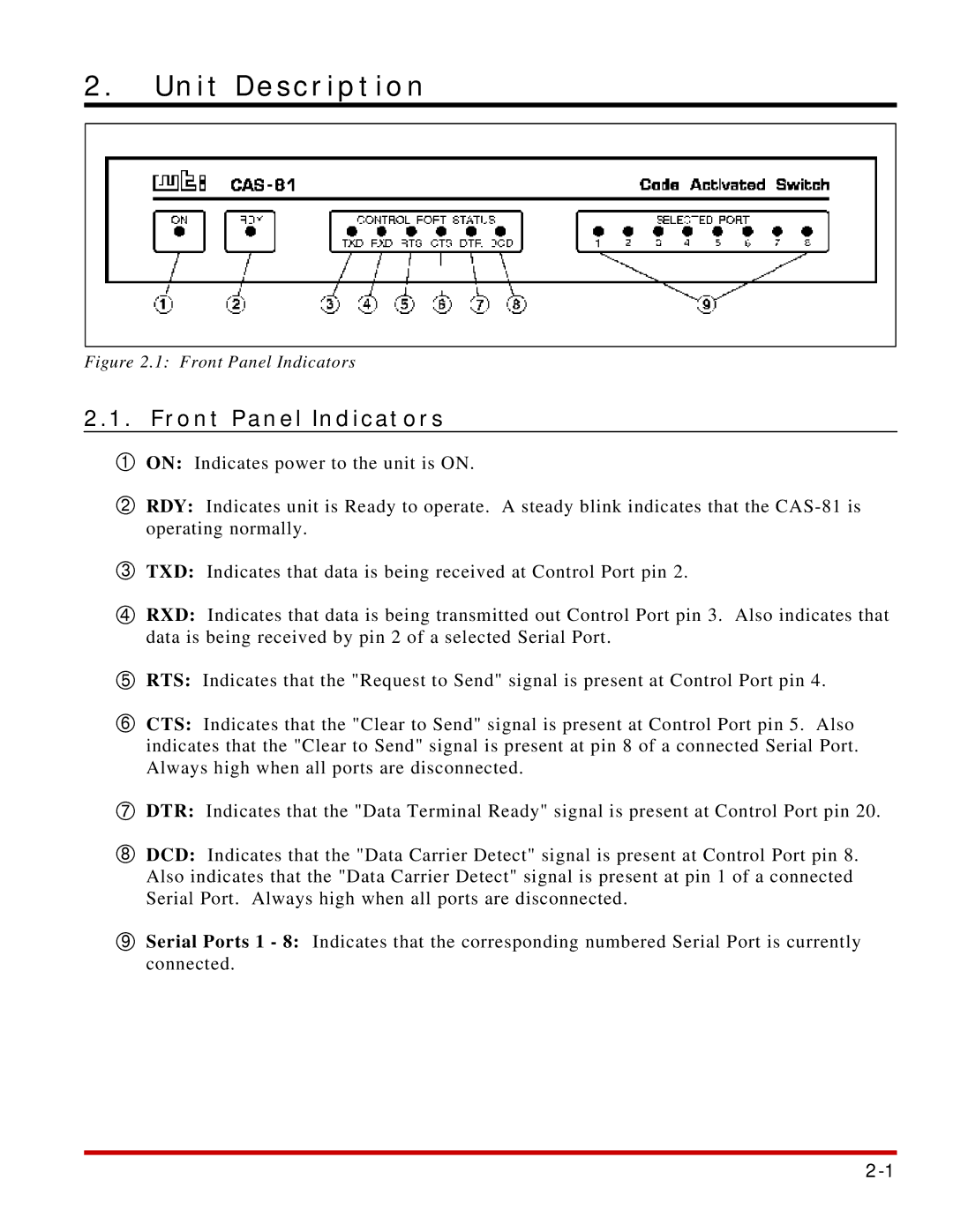
Figure 2.1: Front Panel Indicators
2.1.Front Panel Indicators
ÀON: Indicates power to the unit is ON.
ÁRDY: Indicates unit is Ready to operate. A steady blink indicates that the
ÂTXD: Indicates that data is being received at Control Port pin 2.
ÃRXD: Indicates that data is being transmitted out Control Port pin 3. Also indicates that data is being received by pin 2 of a selected Serial Port.
ÄRTS: Indicates that the "Request to Send" signal is present at Control Port pin 4.
ÅCTS: Indicates that the "Clear to Send" signal is present at Control Port pin 5. Also indicates that the "Clear to Send" signal is present at pin 8 of a connected Serial Port. Always high when all ports are disconnected.
ÆDTR: Indicates that the "Data Terminal Ready" signal is present at Control Port pin 20.
ÇDCD: Indicates that the "Data Carrier Detect" signal is present at Control Port pin 8. Also indicates that the "Data Carrier Detect" signal is present at pin 1 of a connected Serial Port. Always high when all ports are disconnected.
ÈSerial Ports 1 - 8: Indicates that the corresponding numbered Serial Port is currently connected.