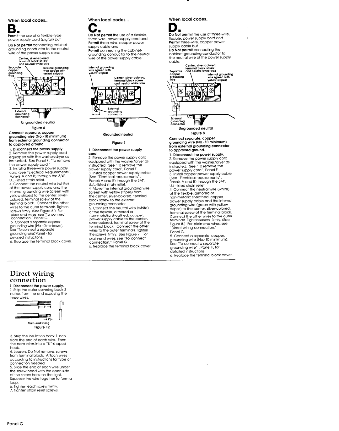
When local codes..
B.
Permit the use of a
power supply cord (pigtail) but
Do Nol permrt connecting cabrnet-
grounding conductor to the neutral wire of the power supply cord:
| Ungrounded |
| neutral |
| |||
|
|
| Figure | 6 |
|
| |
Connect | seporole. | copper |
| ||||
grounding |
| wire | minimum) | ||||
from external | grounding | connector | |||||
to | approved |
| ground. |
|
|
| |
I, | Disconnect | Ihe | power | supply. | |||
2. | Remove |
| the | power | supply | cord | |
equipped |
| with | the | washer/dryer | as | ||
instructed. |
| See | Panel | F, “To remove | |||
the | power |
| supply |
| cord | ” |
|
3.Install a
4.Connect the neutral wire (white) of the power supply cord and the
internal grounding wire (green with yellow stripes) to the center. sliver-
colored, terminal screw of the
terminal block Connect the other wires to the outer terminals.Tighten screws firmly (See Figure 6 1 For
connection: |
| Panel | G. |
| ||
5 | Connect | a separate | copper |
| ||
grounding | wire | (No. | IO | minimum) |
| |
See | “Toconnect | a separate |
| |||
grounding | wIrerPanel |
| F for |
| ||
detolled | Instructions. |
|
|
| ||
6. Replace | the | terminal | block | cover. | ||
Direct | wiring |
|
| ||||
connection |
|
|
| ||||
1. | Disconnect | the | power | supply. |
| ||
2 | Strip | the | outer | covering | back | 3 | |
inches | from | the | end | exposing | the | ||
three | wires. |
|
|
|
|
| |
|
|
|
|
|
| ||
|
|
|
|
|
|
| |
| LIZ |
|
|
| i |
| |
|
|
|
|
| |||
|
|
| Figure | 12 |
|
| |
3.Srrlp the Insulation back 1 inch from the end of each wire. Form the bare wires into a
4.Loosen. Do Not remove. screws
from terminal block. Attach wires
according to instructions for type of
connection needed
5.Slide the end of each wire under the screw head with the open side of the screw hook on the right.
Squeeze the wire together to form a loop.
6Tighten each screw firmly.
7.Tlghten strain relief screws.
When local codes...
c.
Do Not permit the use of a flexible.
Permit
Permit connecting the cabinet-
grounding conductor to the neutral w!re of the power supply cable:
tnternat grounding wire (green with yellow rlrip%r)
center.
\and neutral white wile
|
|
|
| Grounded | neutral |
|
|
| |||||
|
|
|
|
|
| Figure | 7 |
|
|
|
| ||
I. | Disconnect |
| the | power | supply |
| |||||||
cord. |
|
|
|
|
|
|
|
|
|
|
|
| |
2 | Remove |
| the | power |
| supply |
| cord | |||||
equipped |
|
| with | the | washer/dryer |
| as | ||||||
Instructed. |
| See | “To remove |
| the |
| |||||||
power | supply | Panel | F. |
| |||||||||
3. | Install |
| copper | power |
| supply | cable | ||||||
(See | “Electrical | requirements”. |
|
|
| ||||||||
Panels | A | and | 8) through | the | 3/4’. |
| |||||||
| strain | relief. |
|
|
|
|
| ||||||
4 | Move |
| the | internal |
| grounding |
| wire | |||||
tareen | with |
| vellow | stripes) | from |
| |||||||
i6e |
| center, |
|
| terminal |
| |||||||
block |
| screw |
| to | the | external |
|
|
| ||||
grounding |
| connector. |
|
|
|
|
| ||||||
5 | Connect |
|
| the | neutral |
| wire |
| (white) | ||||
of | the | flexible, | armored |
| or |
|
|
| |||||
|
| sheathed, |
| cooper. |
| ||||||||
power | supply |
| cable |
| to | the | center. |
| |||||
|
| terminal |
| screw | of | the | |||||||
terminal |
| block. | Connect | the | other | ||||||||
wires | to | the | outer | terminalsTighten |
| ||||||||
the | screws | firmly | See |
| Figure |
| 7. | For | |||||
| wires, | see | “To connect |
| |||||||||
connection.’ |
|
|
| Panel | G. |
|
|
| |||||
6. | Replace |
|
| the | terminal | block | cover. | ||||||
When local codes...
D n
Do | Not | oermit |
| the | use | of | ||||
flex!bie.‘power |
|
| supply | cord |
| and | ||||
Permit |
| copper |
| Power | ||||||
supply | cable | but |
|
|
|
|
| |||
Do | Not | permit |
| connecting |
|
| the | |||
|
| conductor |
| to | ||||||
the | neutral | wire | of | the | power | supply | ||||
cable: |
|
|
|
|
|
|
|
|
| |
|
|
| Cente,. |
|
|
| ||||
|
|
| terminal | block | screw |
|
| |||
Sepmate |
| and | neutral | while | wtre |
| ||||
copper |
|
|
|
|
| Internal | groundtng | |||
grounding |
|
|
|
|
| wtre | (green with | |||
\ wtre |
|
|
| \ |
|
| yellow |
| stripes) | |
Ungrounded neutral
Figure 8
Connect saparale, copper
grounding wire
from external grounding connector
to | approved | ground. |
|
|
1, | Disconnect | the power | supply. | |
2. | Remove | the power | supply | cord |
equipped |
| with | the | washer/dryer | as | |||||
Instructed. |
| See | “To remove | the | ||||||
power |
| supply | cord”, | Panel | F. |
| ||||
3 | Install | copper |
| power | supply | cable | ||||
(See | “Electrical |
| requirements”. |
|
| |||||
Panels |
| A | and | B) | through | the |
| 3/4’. | ||
| strain |
| relief. |
|
|
| ||||
4 | Connect | the |
| neutral | wire | (white) | ||||
of | the | flexible, | armored | or |
|
| ||||
sheathed. | copper. | |||||||||
power |
| supply | cable | and | the | internal | ||||
grounding |
| wire |
| (green | with | yellow | ||||
strrpes) | to | the | center, | |||||||
terminal | screw | of the terminal |
| block. | ||||||
Connect |
| the other | wires | to | the outer | |||||
terminals, |
| Tighten | screws | firmly. | (See | |||||
Fiaure |
| 8.1 | For | wires. | see | |||||
| V~ |
|
|
|
|
|
|
|
|
|
“Direct | wiring | cOnneC~lOn.~ |
|
| ||||||
Panel | G. |
|
|
|
|
|
|
| ||
5. | Connect | a | separate. | copper. | ||||||
grounding |
| wire | minimum). | |||||||
See | ‘~To connect |
| a | separate |
|
| ||||
grounding |
| wire’ | , Panel | F. for |
| |||||
detailed |
| Instructions. |
|
|
|
| ||||
6 | Replace | the |
| terminal | block | cover. | ||||