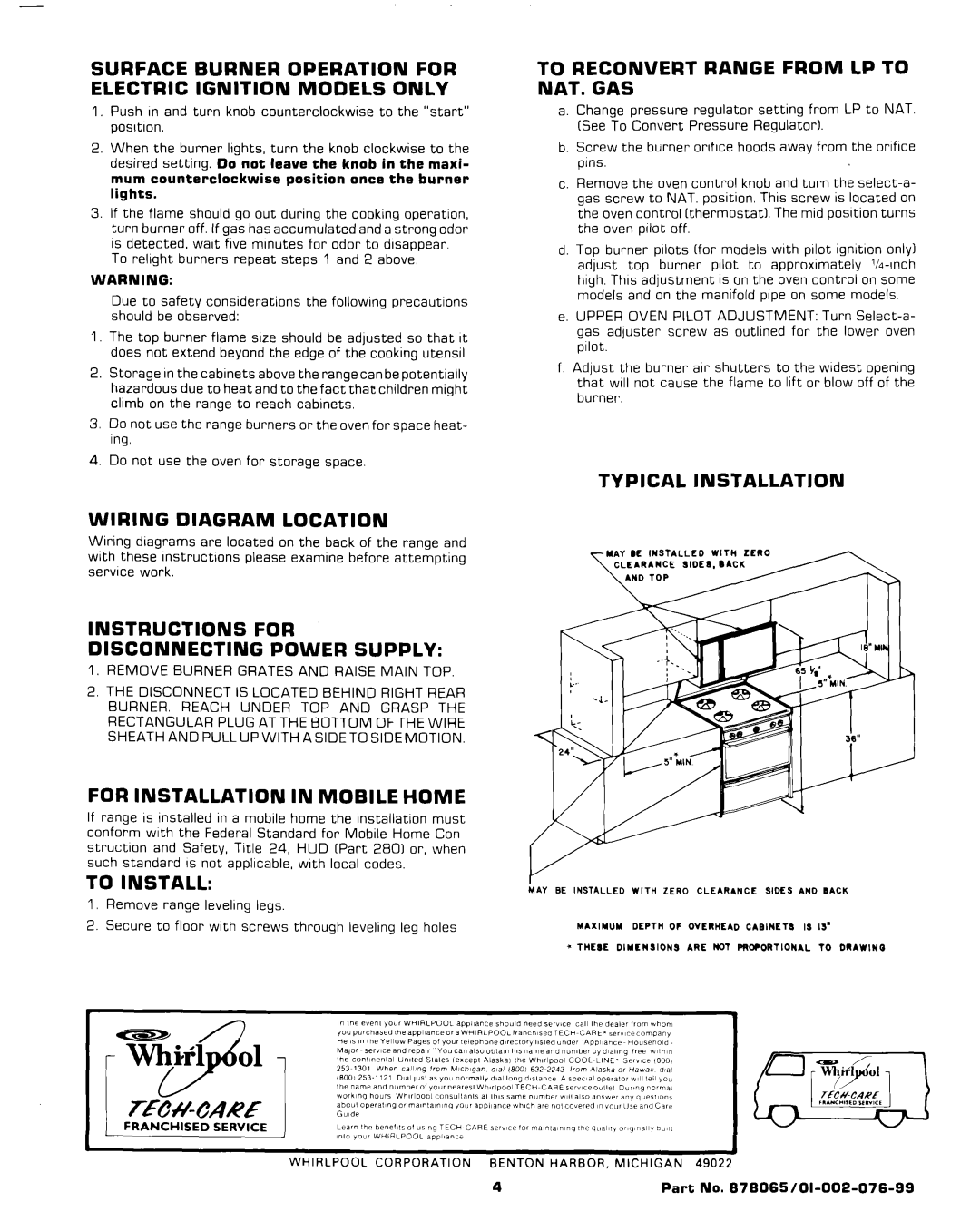
Range specifications
Whirlpool has long been a trusted name in home appliances, and its range of cooktops is no exception. Whether you're preparing a family meal or hosting a dinner party, a Whirlpool range combines practicality and advanced technology to enhance your cooking experience.One of the standout features of Whirlpool ranges is their versatility. Many models offer a combination of gas and electric cooking options, allowing users to choose how they want to prepare their meals. The Gas Burners deliver precise heat control, enabling chefs to achieve the perfect simmer or rapid boiling, while the electric ovens provide even baking and roasting results.
The True Convection technology is another significant feature that sets Whirlpool ranges apart. This system uses a fan and an additional heating element to circulate hot air throughout the oven, ensuring food is cooked evenly on every rack. This is particularly beneficial for multi-layered baking or when cooking multiple dishes at once.
Whirlpool also addresses the need for convenience in the kitchen with features like the Fast Preheat setting that allows the oven to reach the desired temperature in a fraction of the time. Programmable controls, including touch-screen interfaces on select models, make it easy to set cooking times and temperatures accurately.
Cleaning is often a concern with ranges, but Whirlpool incorporates innovative technologies such as the self-cleaning oven feature. This technology uses high temperatures to burn off food residues, leaving behind only ash that can be easily wiped away. Additionally, many models have a fingerprint-resistant finish, keeping the surface clear of smudges and making maintenance a breeze.
Safety is another critical characteristic of Whirlpool ranges. Many units feature a control lock that prevents accidental operation and ensures peace of mind in households with children.
Moreover, Whirlpool's commitment to energy efficiency is evident in their range designs. They integrate eco-friendly appliances that minimize energy consumption, helping families save on utility bills while reducing their environmental impact.
In summary, Whirlpool ranges incorporate various features and technologies designed to enhance cooking performance, convenience, and safety. With options that cater to both amateur cooks and seasoned chefs, Whirlpool continues to deliver high-quality kitchen solutions that meet the diverse needs of modern households.

