4 MOUNTING AND WIRING

CONTINUED FROM SECOND PAGE

O/B

Y

G

W2

E

Changeover


See Note **


Fan


Emergency

Relay*

Compressor

Aux

Relay

Relay


Relay


Contactor


(Stage 2)


*Changeover Relay is energized in COOL when O/B switch is in the “O” position Changeover Relay is energized in HEAT when O/B switch is in the “B” position

**Jumper required to use a single Aux Heat for both Second Stage Heat and Emergency

THERMOSTAT

CL R

SYSTEM

SYSTEM

MONITOR

SWITCH

Hot

24 VAC

120 VAC

Neutral

TRANSFORMER

(Class II)

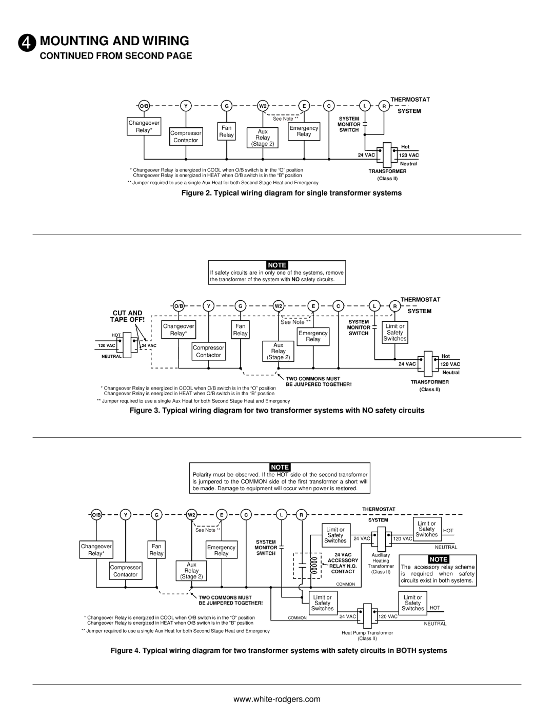
Figure 2. Typical wiring diagram for single transformer systems

NOTE

If safety circuits are in only one of the systems, remove the transformer of the system with NO safety circuits.


O/B

Y

G

W2

E

C

L

CUT AND


TAPE OFF!

Changeover


Fan

See Note **


SYSTEM


Emergency


MONITOR

HOT


Relay*


Relay


SWITCH


Aux

Relay


120 VAC

24 VAC

Compressor


Relay


NEUTRAL


Contactor


(Stage 2)


TWO COMMONS MUST


BE JUMPERED TOGETHER!

*Changeover Relay is energized in COOL when O/B switch is in the “O” position Changeover Relay is energized in HEAT when O/B switch is in the “B” position

THERMOSTAT

R

SYSTEM

Limit or

Safety

Switches

24 VAC


Hot


120 VAC

Neutral

TRANSFORMER

(Class II)

** Jumper required to use a single Aux Heat for both Second Stage Heat and Emergency

Figure 3. Typical wiring diagram for two transformer systems with NO safety circuits

NOTE

Polarity must be observed. If the HOT side of the second transformer is jumpered to the COMMON side of the first transformer a short will be made. Damage to equipment will occur when power is restored.


THERMOSTAT


O/B


Y


G


W2


E

C


L

R


SYSTEM


Limit or


See Note **


Limit or


Safety


HOT


Safety


24 VAC


120 VAC

Switches


SYSTEM


Switches


Changeover


Fan


Emergency


MONITOR


NEUTRAL

Relay*


Relay


Relay


SWITCH


24 VAC


Auxiliary


ACCESSORY


Heating


NOTE


Compressor


Aux


RELAY N.O.


Transformer

The


accessory relay scheme


Relay


Contactor


CONTACT


(Class II)


is

required

when safety


(Stage 2)


circuits exist in both systems.


COMMON


TWO COMMONS MUST


Limit or


Limit or


BE JUMPERED TOGETHER!


Safety


Safety

HOT

* Changeover Relay is energized in COOL when O/B switch is in the “O” position


Switches

24 VAC


120 VAC


Switches


COMMON


Changeover Relay is energized in HEAT when O/B switch is in the “B” position


NEUTRAL


** Jumper required to use a single Aux Heat for both Second Stage Heat and Emergency

Heat Pump Transformer


(Class II)

Figure 4. Typical wiring diagram for two transformer systems with safety circuits in BOTH systems

www.white-rodgers.com

Page 3
Image 3
White Rodgers 1F72 installation instructions From Second, Fan Emergency Relay Compressor Aux Contactor Stage

1F72 specifications

The White Rodgers 1F72 is a highly regarded thermostat known for its reliability and advanced features, designed primarily to enhance comfort and energy efficiency in residential heating and cooling systems. A product of White Rodgers, a reputable brand in HVAC controls, the 1F72 is engineered to integrate seamlessly with various HVAC systems while providing intuitive user control.

One of the standout features of the White Rodgers 1F72 is its programmable capabilities. This thermostat allows users to set different temperature schedules for various times of the day and days of the week. Users can easily program it to lower the temperature at night and raise it again in the morning, leading to significant energy savings without sacrificing comfort. The flexible scheduling feature makes it suitable for families with varying routines.

The user interface of the 1F72 is designed for ease of use. It features a large, easy-to-read display that provides clear temperature settings and options. The thermostat’s buttons are intuitive, allowing users to adjust settings with minimal effort. The simple design is especially beneficial for individuals who may not be technically inclined.

Another notable technology incorporated in the White Rodgers 1F72 is the Smart Recovery feature. This innovative capability enables the thermostat to start heating or cooling the home before the programmed time, ensuring that the desired temperature is reached just when it's needed. This proactive approach contributes to improved energy efficiency.

The 1F72 is compatible with a wide range of heating and cooling systems, including conventional systems, heat pumps, and multi-stage systems. This versatility makes it an excellent choice for different types of homes and setups.

In addition to its programmable functionality, the thermostat also features advanced temperature control capabilities. With the precision of its temperature sensor, the 1F72 ensures that the home's temperature remains as consistent as possible, enhancing comfort and reducing energy waste.

Overall, the White Rodgers 1F72 thermostat is an exemplary device for anyone looking to manage their home’s heating and cooling needs effectively. With its programmable schedules, user-friendly interface, and compatibility with various systems, it stands out as an optimal solution for modern HVAC control demands.