CB O

NOTE

For 2-wire Heat only, attach to RH and W


JUMPER


WIRE


Y

G

W

RC RH

THERMOSTAT

SYSTEM


Fan

Heating


Relay

System


Hot


24 VAC

120 VAC


Neutral


TRANSFORMER

THERMOSTAT

CB O

Y

G

W

RC RH

Cooling

Fan

Heating

System

Relay

System


SYSTEM


Hot


24 VAC


120 VAC


Neutral


HEATING

TRANSFORMER

24 VAC


Hot


120 VAC

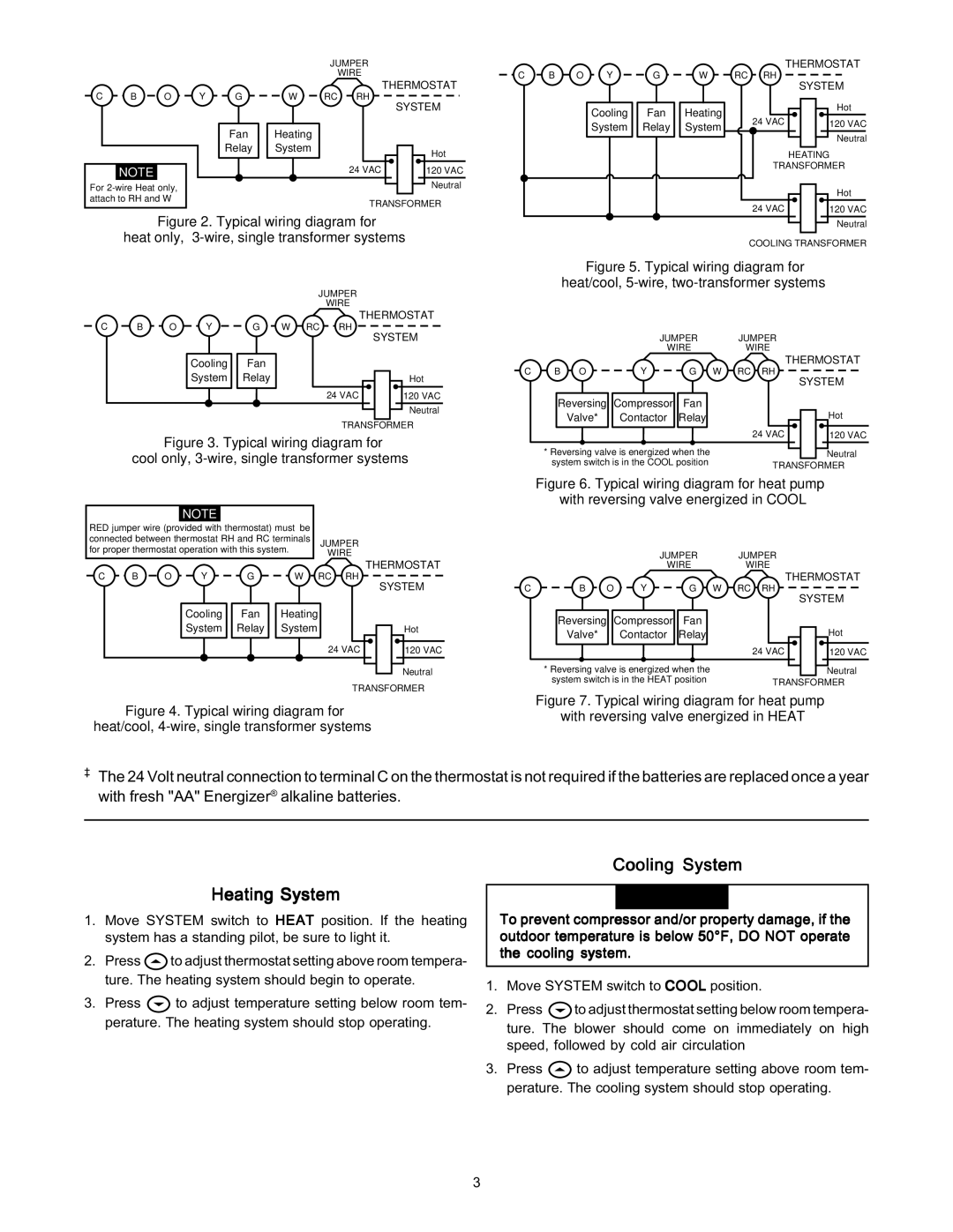
Figure 2. Typical wiring diagram for

heat only, 3-wire, single transformer systems

JUMPER

WIRE

C


Y


THERMOSTAT


B

O


G

W

RC

RH


SYSTEM


Cooling


Fan


System


Relay


Hot


24 VAC


120 VAC


Neutral


TRANSFORMER


Figure 3. Typical wiring diagram for


cool only, 3-wire, single transformer systems


NOTE


RED jumper wire (provided with thermostat) must be


connected between thermostat RH and RC terminals


JUMPER


for proper thermostat operation with this system.


WIRE


C

B

O


Y


G

W


RC

RH

THERMOSTAT


SYSTEM


Cooling


Fan


Heating


System


Relay


System


Hot


24 VAC


120 VAC


Neutral


TRANSFORMER


Neutral

COOLING TRANSFORMER

Figure 5. Typical wiring diagram for

heat/cool, 5-wire, two-transformer systems

JUMPER JUMPER

WIREWIRE

C

B O


Y

G

W

RC RH

THERMOSTAT


SYSTEM


Reversing

Compressor

Fan


Valve*


Contactor

Relay


Hot


24 VAC

120 VAC


* Reversing valve is energized when the


Neutral


system switch is in the COOL position


TRANSFORMER


Figure 6. Typical wiring diagram for heat pump


with reversing valve energized in COOL


JUMPER


JUMPER


WIRE


WIRE


C

B O

Y

G

W

RC RH

THERMOSTAT

SYSTEM


Reversing

Compressor

Fan


Valve*


Contactor

Relay


Hot


24 VAC

120 VAC


* Reversing valve is energized when the


Neutral


system switch is in the HEAT position


TRANSFORMER

Figure 7. Typical wiring diagram for heat pump

Figure 4. Typical wiring diagram forwith reversing valve energized in HEAT heat/cool, 4-wire, single transformer systems

The 24 Volt neutral connection to terminal C on the thermostat is not required if the batteries are replaced once a year with fresh "AA" Energizer® alkaline batteries.

Heating System

1.Move SYSTEM switch to HEAT position. If the heating system has a standing pilot, be sure to light it.

2.Press to adjust thermostat setting above room tempera- ture. The heating system should begin to operate.

3.Press to adjust temperature setting below room tem- perature. The heating system should stop operating.

Cooling System

! CAUTION

To prevent compressor and/or property damage, if the outdoor temperature is below 50°F, DO NOT operate the cooling system.

1.Move SYSTEM switch to COOL position.

2.Press to adjust thermostat setting below room tempera- ture. The blower should come on immediately on high speed, followed by cold air circulation

3.Press to adjust temperature setting above room tem- perature. The cooling system should stop operating.

3

Page 3
Image 3
White Rodgers 1F80-361 specifications Heating System, Cooling System

1F80-361 specifications

The White Rodgers 1F80-361 is a state-of-the-art digital thermostat designed to provide optimal control over home heating and cooling systems. This versatile unit is suitable for various HVAC systems, making it a popular choice among homeowners looking for efficient climate management.

One of the main features of the 1F80-361 is its intelligent touchscreen interface, which simplifies the user experience. The bright, easy-to-read display allows users to quickly access and adjust settings, making temperature regulation a seamless task. The interface provides clear prompts for programming, ensuring that even those less technologically inclined can navigate it with ease.

Energy efficiency is a key characteristic of the 1F80-361, as it incorporates advanced algorithms to optimize heating and cooling schedules according to the homeowner's lifestyle. The thermostat is equipped with a 7-day programmable feature that enables users to set different temperature settings for each day of the week. This functionality maximizes energy savings by allowing the system to run less during times when the home is unoccupied.

An important technological aspect of the White Rodgers 1F80-361 is its compatibility with a variety of heating and cooling systems, including gas, electric, and heat pump systems. This broad compatibility means that many homeowners can upgrade to this smart thermostat without needing extensive modifications to their existing systems.

Additionally, the 1F80-361 features a built-in Wi-Fi capability that allows users to access and control their thermostat remotely through a mobile app. This connectivity provides homeowners with added convenience, as they can adjust their home's temperature from anywhere, ensuring comfort upon arrival.

Another noteworthy characteristic is the programmable fan option, which allows for continuous air circulation, enhancing comfort while also improving indoor air quality. The system can automatically activate the fan to distribute air more evenly throughout the home, reducing hot or cold spots.

Moreover, the thermostat includes alerts for maintenance reminders, helping homeowners stay proactive about their HVAC system care. The intuitive design and thoughtful features of the White Rodgers 1F80-361 combine to deliver an advanced and user-friendly solution for residential climate control, ultimately leading to enhanced comfort and energy savings.