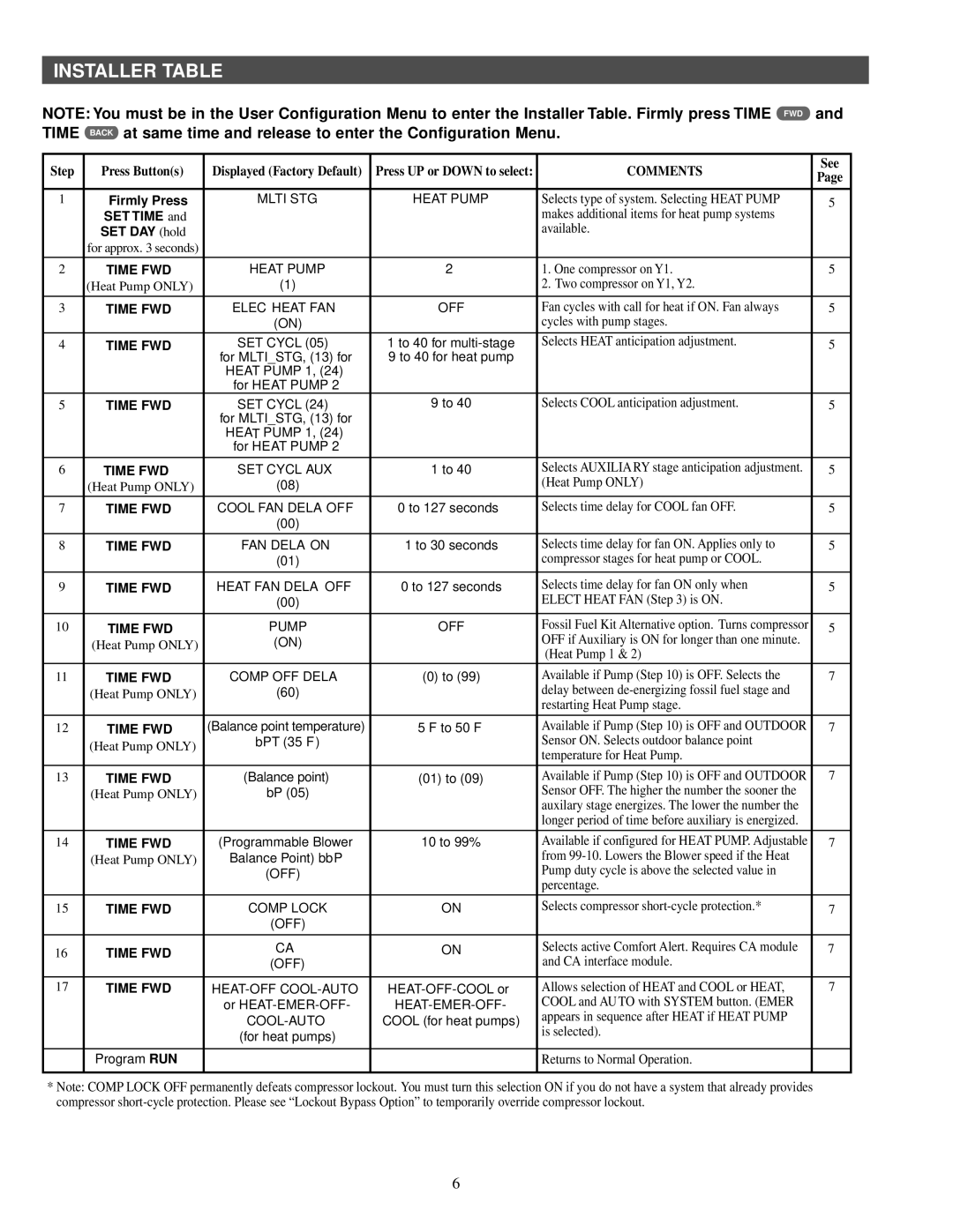
1F95CA-391 specifications
The White Rodgers 1F95CA-391 is a multifunctional smart thermostat designed to offer homeowners greater control over their heating and cooling systems. As part of the HVAC industry’s move toward smarter technology, this device blends user-friendly features with advanced automation to enhance energy efficiency and comfort.One of the standout features of the White Rodgers 1F95CA-391 is its compatibility with multiple heating and cooling systems. It supports conventional, heat pump, and auxiliary heat setups, making it versatile for a wide range of homes and setups. This flexibility ensures that virtually any homeowner can easily integrate it into their existing HVAC system without extensive modifications.
The thermostat boasts a user-friendly touchscreen interface that simplifies programming and daily adjustments. The intuitive design allows users to set schedules based on their daily routines easily. This feature ensures that heating and cooling systems operate only when needed, thereby reducing energy consumption and lowering utility bills.
Another key characteristic of the White Rodgers 1F95CA-391 is its Wi-Fi connectivity. This technology enables homeowners to monitor and control their thermostats remotely via a smartphone or tablet. Users can adjust temperatures, view system status, and even receive alerts about potential issues, ensuring peace of mind and convenience.
Energy-saving technologies are also at the forefront of the White Rodgers 1F95CA-391’s design. It incorporates energy-saving algorithms that learn user preferences and adjust heating and cooling schedules accordingly. Additionally, features such as two-stage heating and cooling management enhance performance while helping to optimize energy consumption.
The White Rodgers 1F95CA-391 is equipped with advanced filtration reminders that alert users when it’s time to change the HVAC system’s filters. Regular filter changes not only prolong the life of the system but also improve indoor air quality.
Lastly, the device is designed with a sleek and modern aesthetic, making it a stylish addition to any home decor. The clear display is easy to read, and the overall design is compact, allowing it to blend seamlessly within any environment.
In summary, the White Rodgers 1F95CA-391 thermostat combines cutting-edge technology with ease of use. Its compatibility with various HVAC systems, remote access capabilities, and focus on energy efficiency make it a valuable investment for any homeowner looking to enhance comfort while optimizing energy use.

