INSTALLATION
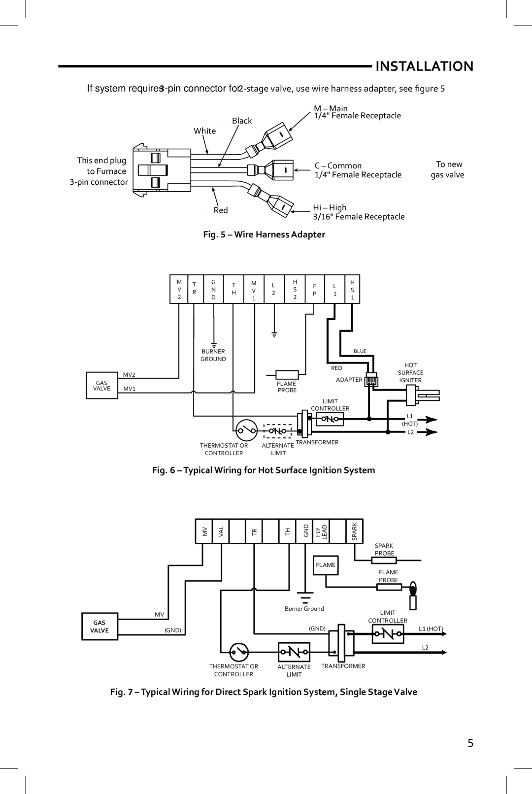
If system requires
|
|
|
|
|
|
|
|
|
|
|
|
|
| M – Main |
|
|
|
|
|
|
|
|
|
| |
|
|
|
|
|
|
| Black |
|
|
|
|
| 1/4" Female Receptacle |
|
|
| |||||||||
|
|
| White |
|
|
|
|
|
|
|
|
|
|
|
|
|
|
|
|
| |||||
|
|
|
|
|
|
|
|
|
|
|
|
|
|
|
|
|
|
|
|
|
| ||||
This end plug |
|
|
|
|
|
|
|
|
|
|
| C – Common |
|
|
|
|
|
| To new | ||||||
| to Furnace |
|
|
|
|
|
|
|
|
|
|
|
|
|
|
|
|
| |||||||
|
|
|
|
|
|
|
|
|
|
|
| 1/4" Female Receptacle | gas valve | ||||||||||||
|
|
|
|
|
|
|
|
|
|
|
| ||||||||||||||
|
|
|
|
|
|
|
|
|
|
|
|
|
|
|
|
|
|
|
|
|
|
| |||
|
|
|
|
| Red |
|
|
|
|
|
|
| Hi – High |
|
|
|
|
|
|
|
|
|
| ||
|
|
|
|
|
|
|
|
|
|
|
|
|
| 3/16" Female Receptacle |
|
|
| ||||||||
|
|
|
| Fig. 5 – Wire Harness Adapter |
|
|
|
|
|
|
|
|
|
|
| ||||||||||
|
| M | T |
| G | T | M | L | H | F | L | H |
|
|
|
|
|
|
|
|
| ||||
|
| V |
| N | V |
| S | S |
|
|
|
|
|
|
|
|
| ||||||||
|
| R |
| H | 2 |
| P | 1 |
|
|
|
|
|
|
|
|
| ||||||||
2 |
| D | 1 | 2 | 1 |
|
|
|
|
|
|
|
|
| |||||||||||
|
|
|
|
|
|
|
|
|
|
|
|
|
|
|
| ||||||||||
|
|
|
|
|
|
|
|
|
|
|
|
|
|
|
|
|
|
|
|
|
|
|
| ||
|
|
|
|
|
|
|
|
|
|
|
|
|
|
|
|
|
|
|
|
|
|
|
|
|
|
|
|
|
|
|
|
|
|
|
|
|
|
|
|
|
|
|
|
|
|
|
|
|
|
|
|
|
|
|
| BURNER |
|
|
|
|
|
|
|
|
| BLUE |
|
|
|
|
|
|
|
|
| ||
|
|
|
| GROUND |
|
|
|
|
|
|
|
|
|
| HOT |
|
|
| |||||||
|
|
|
|
|
|
|
|
|
|
|
|
|
|
| RED |
|
|
|
| ||||||
|
| MV2 |
|
|
|
|
|
|
|
|
|
|
|
|
| SURFACE |
|
|
| ||||||
|
|
|
|
|
|
|
|
|
|
|
|
|
| ADAPTER |
|
|
| ||||||||
|
|
|
|
|
|
|
|
|
|
|
|
|
| IGNITER |
|
|
| ||||||||
| GAS |
|
|
|
|
|
|
|
| FLAME |
|
|
|
| |||||||||||
| VALVE MV1 |
|
|
|
|
|
|
|
| PROBE |
|
|
|
|
|
|
|
|
|
|
|
| |||
LIMIT |
CONTROLLER |
L1 |
(HOT) |
L2 |
THERMOSTAT OR | ALTERNATE TRANSFORMER |
CONTROLLER | LIMIT |
Fig. 6 – Typical Wiring for Hot Surface Ignition System
GAS |
VALVE |
MV | VAL | TR | TH | GND | FLY LEAD | SPARK |
|
|
|
|
|
| SPARK |
|
|
|
|
|
| PROBE |
|
|
|
|
| FLAME | FLAME |
|
|
|
|
|
| |
|
|
|
|
|
| PROBE |
MV | Burner Ground | LIMIT |
| ||
|
| CONTROLLER |
(GND) | (GND) | L1 (HOT) |
|
| L2 |
THERMOSTAT OR | ALTERNATE TRANSFORMER |
|
CONTROLLER | LIMIT |
|
Fig. 7 – Typical Wiring for Direct Spark Ignition System, Single Stage Valve
5
