MAIN PIPING CONNECTIONS
NOTE
Refer to warnings and cautions on page 2 before attempting installation. All piping must comply with local codes, ordinances, and/or national fuel gas codes.
1.Turn off electrical power to the system at the fuse box or circuit breaker. Also turn off the main gas supply.
2. If replacing an existing valve, disconnect all plumbing and electrical connections from the old control.
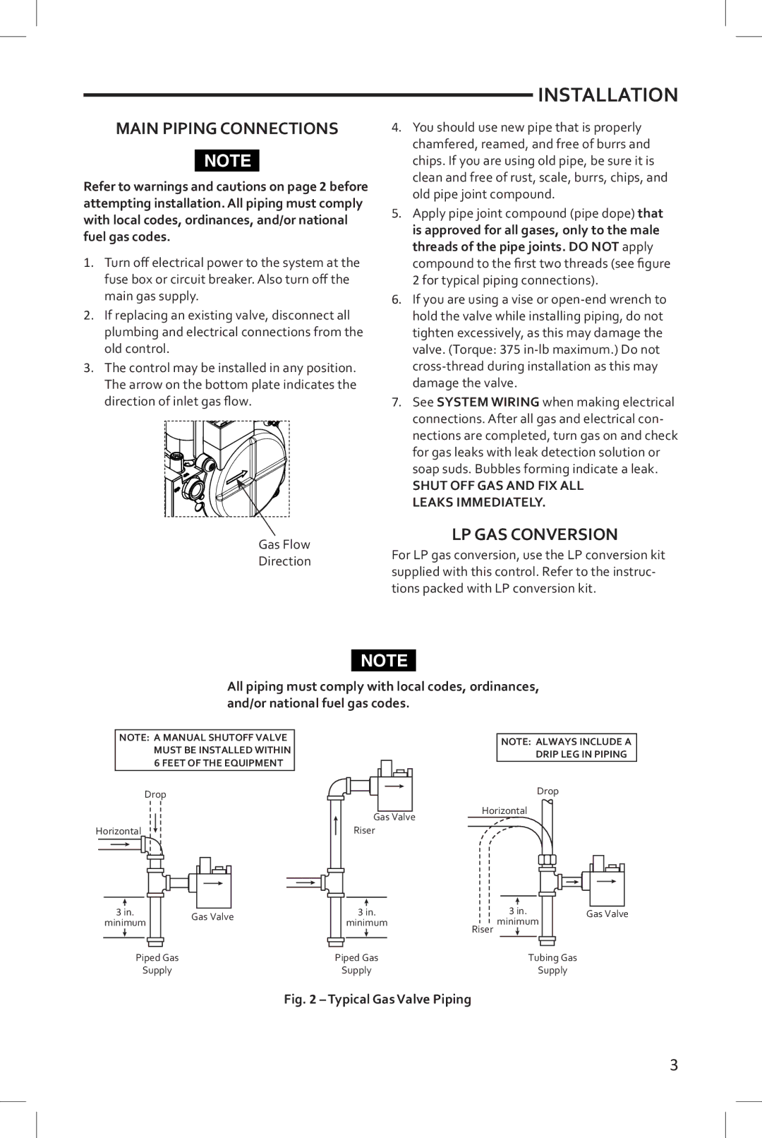
3.The control may be installed in any position. The arrow on the bottom plate indicates the direction of inlet gas flow. ![]()
Gas Flow
Direction
INSTALLATION
4.You should use new pipe that is properly chamfered, reamed, and free of burrs and chips. If you are using old pipe, be sure it is clean and free of rust, scale, burrs, chips, and old pipe joint compound.
5.Apply pipe joint compound (pipe dope) that is approved for all gases, only to the male threads of the pipe joints. DO NOT apply compound to the first two threads (see figure
2 for typical piping connections).
6.If you are using a vise or
7.See SYSTEM WIRING when making electrical connections. After all gas and electrical con- nections are completed, turn gas on and check for gas leaks with leak detection solution or soap suds. Bubbles forming indicate a leak.
SHUT OFF GAS AND FIX ALL LEAKS IMMEDIATELY.
LP GAS CONVERSION
For LP gas conversion, use the LP conversion kit supplied with this control. Refer to the instruc- tions packed with LP conversion kit.
NOTE
All piping must comply with local codes, ordinances, and/or national fuel gas codes.
NOTE: A MANUAL SHUTOFF VALVE MUST BE INSTALLED WITHIN 6 FEET OF THE EQUIPMENT
Drop
Horizontal
3 in. |
|
|
| Gas Valve | |
minimum |
|
|
| ||
|
|
|
| ||
|
|
|
|
|
|
|
|
|
|
|
|
Piped Gas
Supply
NOTE: ALWAYS INCLUDE A
DRIP LEG IN PIPING
Drop
Gas Valve | Horizontal |
| |
Riser |
|
|
|
| 3 in. | 3 in. |
|
| Gas Valve |
|
|
| minimum | Riser minimum |
| ||
|
|
|
|
|
|
|
|
| Piped Gas | Tubing Gas |
| ||||
|
| Supply | Supply |
| |||
Fig. 2 – Typical Gas Valve Piping
3