INSTALLATION CONT.

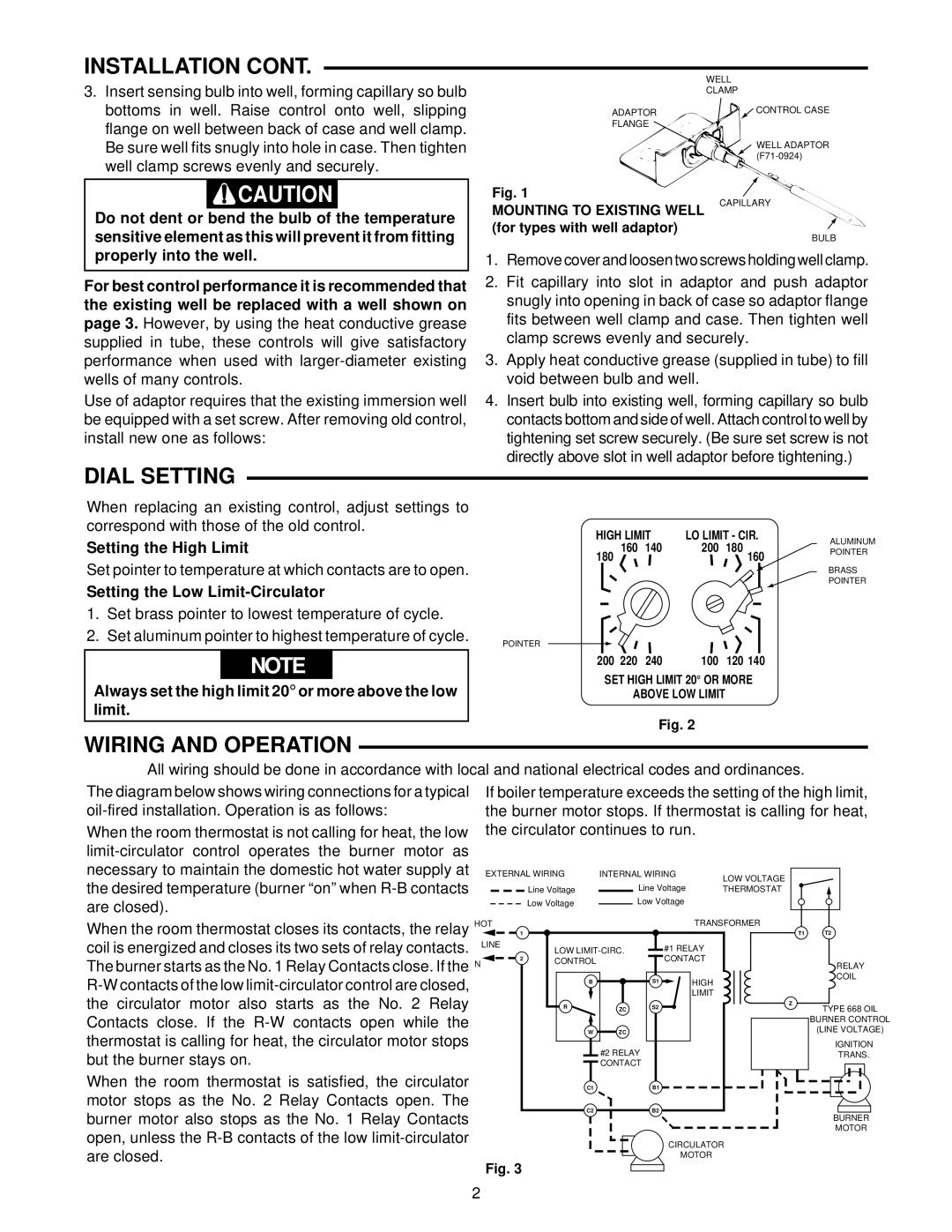
3.Insert sensing bulb into well, forming capillary so bulb bottoms in well. Raise control onto well, slipping flange on well between back of case and well clamp. Be sure well fits snugly into hole in case. Then tighten well clamp screws evenly and securely.

WELL

CLAMP

ADAPTOR

CONTROL CASE


FLANGE


WELL ADAPTOR


(F71-0924)

CAUTION

Do not dent or bend the bulb of the temperature sensitive element as this will prevent it from fitting

Fig. 1

MOUNTING TO EXISTING WELL (for types with well adaptor)

CAPILLARY

BULB

properly into the well.

For best control performance it is recommended that the existing well be replaced with a well shown on page 3. However, by using the heat conductive grease supplied in tube, these controls will give satisfactory performance when used with larger-diameter existing wells of many controls.

Use of adaptor requires that the existing immersion well be equipped with a set screw. After removing old control, install new one as follows:

1.Remove cover and loosen two screws holding well clamp.

2.Fit capillary into slot in adaptor and push adaptor snugly into opening in back of case so adaptor flange fits between well clamp and case. Then tighten well clamp screws evenly and securely.

3.Apply heat conductive grease (supplied in tube) to fill void between bulb and well.

4.Insert bulb into existing well, forming capillary so bulb contacts bottom and side of well. Attach control to well by tightening set screw securely. (Be sure set screw is not directly above slot in well adaptor before tightening.)

DIAL SETTING

When replacing an existing control, adjust settings to


correspond with those of the old control.

HIGH LIMIT

LO LIMIT - CIR.

Setting the High Limit

160 140

200 180


180

160

Set pointer to temperature at which contacts are to open.

Setting the Low Limit-Circulator

1. Set brass pointer to lowest temperature of cycle.

2. Set aluminum pointer to highest temperature of cycle.

POINTER


NOTE

200

220

240

100

120 140

SET HIGH LIMIT 20° OR MORE

Always set the high limit 20° or more above the low


ABOVE LOW LIMIT


limit.


Fig. 2


ALUMINUM POINTER

BRASS POINTER

WIRING AND OPERATION

All wiring should be done in accordance with local and national electrical codes and ordinances.

The diagram below shows wiring connections for a typical oil-fired installation. Operation is as follows:

When the room thermostat is not calling for heat, the low limit-circulator control operates the burner motor as necessary to maintain the domestic hot water supply at the desired temperature (burner “on” when R-B contacts are closed).

If boiler temperature exceeds the setting of the high limit, the burner motor stops. If thermostat is calling for heat, the circulator continues to run.

EXTERNAL WIRING

INTERNAL WIRING

LOW VOLTAGE


Line Voltage


Line Voltage


THERMOSTAT


Low Voltage


Low Voltage


When the room thermostat closes its contacts, the relay HOT

TRANSFORMER

1

coil is energized and closes its two sets of relay contacts. LINE

LOW LIMIT-CIRC.

#1 RELAY

T1 T2

The burner starts as the No. 1 Relay Contacts close. If the N R-W contacts of the low limit-circulator control are closed, the circulator motor also starts as the No. 2 Relay Contacts close. If the R-W contacts open while the thermostat is calling for heat, the circulator motor stops but the burner stays on.

When the room thermostat is satisfied, the circulator motor stops as the No. 2 Relay Contacts open. The burner motor also stops as the No. 1 Relay Contacts open, unless the R-B contacts of the low limit-circulator

2

CONTROL

B


R

ZC


W

ZC

#2 RELAY

CONTACT

C1

C2

CONTACT

S1

HIGH


LIMIT

S2


B1

B2

RELAY

COIL

Z

TYPE 668 OIL

BURNER CONTROL

(LINE VOLTAGE)

IGNITION

TRANS.

BURNER

MOTOR

are closed.

CIRCULATOR

MOTOR

Fig. 3

2

Page 2
Image 2
White Rodgers 37-5488A, 8B43A-601 specifications Dial Setting, Wiring and Operation

8B43A-601, 37-5488A specifications

The White Rodgers 37-5488A, also known as the 8B43A-601, is a versatile and advanced thermostat designed for efficient climate control in residential and light commercial environments. With its user-friendly interface and cutting-edge technology, this model has become a popular choice for homeowners and HVAC professionals alike.

One of the main features of the 37-5488A thermostat is its compatibility with a variety of heating and cooling systems, including conventional and heat pump systems. This flexibility allows it to be used in diverse settings, accommodating different HVAC configurations. Additionally, the thermostat supports both single and multi-stage heating and cooling, making it suitable for a wide range of applications.

The device is equipped with a digital display that provides clear temperature readings and system status indicators, allowing users to easily monitor and adjust settings as needed. It features an intuitive programming system that enables users to set and modify schedules effortlessly. This functionality helps optimize energy usage and maintain comfortable living conditions at all times, reducing unnecessary energy consumption.

Another significant aspect of the White Rodgers 37-5488A is its advanced algorithms that enhance system efficiency. This thermostat incorporates temperature averaging technology, which ensures accurate readings by factoring in multiple temperature sensors. This results in more precise control of the indoor climate, contributing to increased comfort and energy savings.

Energy efficiency is a key characteristic of the 37-5488A model. It includes various settings that enable users to take advantage of energy-saving modes and programmable options. With the implementation of setback temperatures during non-occupancy hours, homeowners can achieve greater energy efficiency without sacrificing comfort.

Moreover, the device features a user-friendly installation process, with straightforward wiring instructions that make it accessible even for those with limited HVAC experience. The compatibility with common wiring configurations simplifies the replacement of outdated thermostats.

In summary, the White Rodgers 37-5488A, 8B43A-601 model stands out due to its adaptable compatibility, user-friendly interface, advanced temperature sensing technology, energy efficiency features, and easy installation. These attributes combine to make it a reliable and effective thermostat choice, contributing to enhanced comfort and reduced energy costs for users.