Manuals
/
Windsor
/
Household Appliance
/
Vacuum Cleaner
Windsor
10080170, ADM8
operating instructions
Controls/Component Locations, Electrical Cord
Models:
ADM8
10080170
1
9
40
40
Download
40 pages
33.77 Kb
6
7
8
9
10
11
12
13
Troubleshooting
Specification
Wiring Diagram
Maintenance
Accessory Tool Usage
Frame Assembly
Cleaning Procedure
Recovery Tank Assembly
How to
Vacuum Motor Replacement
Page 9
Image 9
Page 8
Page 10
Page 9
Image 9
Page 8
Page 10
Contents
MODEL ADM810080170
Operating Instructions
CARPET EXTRACTOR
86038320 03/16/07 PRV NO
MACHINE DATA LOG/OVERVIEW
YOUR DEALER
MODEL
HOW TO USE THIS MANUAL
TABLE OF CONTENTS
SAFETY
MAINTENANCE
HOW TO USE THIS MANUAL
READ ALL INSTRUCTIONS BEFORE USING THIS MACHINE
SAFETY INSTRUCTIONS
This machine is for commercial use
IMPORTANT SAFETY INSTRUCTIONS
HAZARD INTENSITY LEVEL
HAZARD INTENSITY LEVEL
FOR SAFETY
WHEN SERVICING MACHINE
GROUNDING INSTRUCTIONS
ELECTRICAL
GROUNDING INSTRUCTIONS
POWER TYPE
TECHNICAL SPECIFICATIONS
GENERAL DIMENSIONS/WEIGHT
BRUSH SPEED 1000 rpm
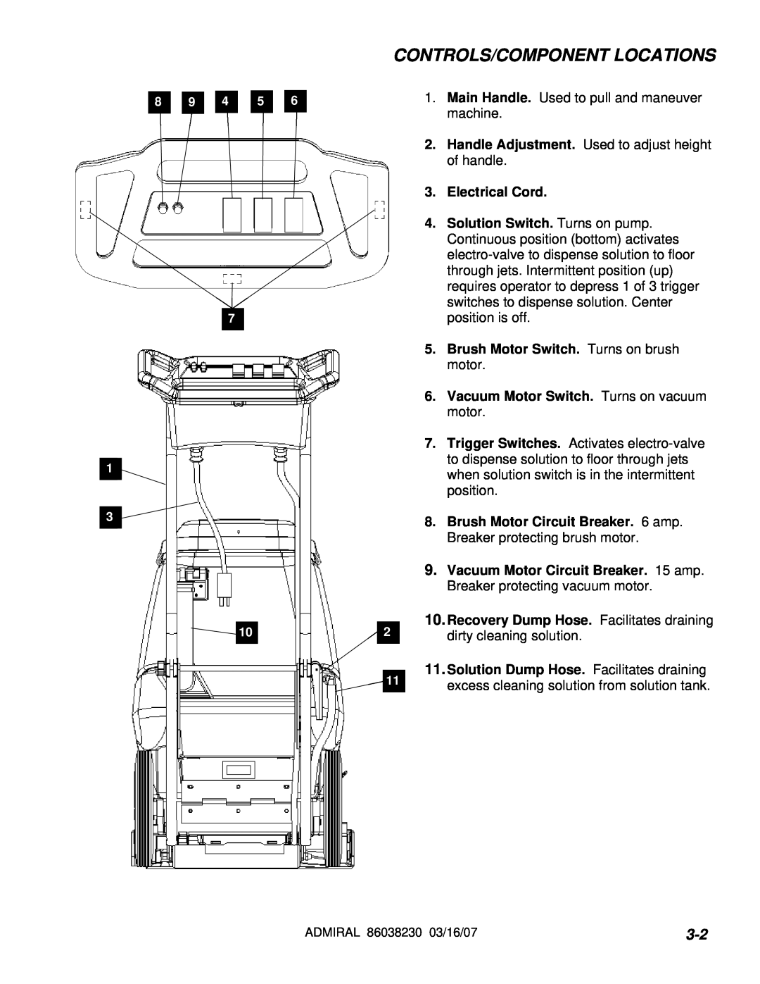
11.Solution Dump Hose. Facilitates draining
10.Recovery Dump Hose. Facilitates draining
CONTROLS/COMPONENT LOCATIONS
3.Electrical Cord
6.Recovery Tank Dome 7.Vacuum Shoe
CONTROLS/COMPONENT LOCATIONS
11 1 9 2
3.Float Shut-Off 4.Clean-OutOpening 5.Pour Spout
1.Solution Intake Cover 2.Vacuum Intake Cover
CONTROLS/COMPONENT LOCATIONS
6.Lift Handle
CHEMICALS
FILLING OPERATIONS
CORRECT INCORRECT
OPERATIONS
OPERATIONS
Adjust handle to comfortable operating
CLEANING PROCEDURE
STEP
CLEANING PROCEDURE
ACCESSORY TOOL USAGE
APRV NO
3-10
MAINTENANCE
SERVICE SCHEDULE
MAINTENANCE
PERIODIC MAINTENANCE
DAILY / REGULAR MAINTENANCE
MAINTENANCE
VACUUM MOTOR REPLACEMENT
Vacuum Motor Carbon Brushes Replacement Windsor
Vacuum Motor Carbon Brushes Replacement Ametek
BELT REPLACEMENT
86249420 PRV NO. 86287330 PRV NO
MAINTENANCE
SOLUTION PUMP REPLACEMENT
MAINTENANCE
86268290
WIRING DIAGRAM
86268460
86268430
PROBLEM
TROUBLESHOOTING CHART
SOLUTION
CAUSE
ADMIRAL 86038230 03/16/07
FRAME ASSEMBLY
SEE PG
SEE PG
FRAME ASSEMBLY
BRUSH ASSEMBLY
16 12
27 19 2030
BRUSH ASSEMBLY
SEE PG
PUMP ASSEMBLY
PUMP ASSEMBLY
ADMIRAL 86038230 03/16/07
VACUUM SHOE ASSEMBLY
VACUUM SHOE ASSEMBLY
SEE PG
CONTROL PANEL ASSEMBLY
CONTROL PANEL ASSEMBLY
5-10
12 12A 10 12B
SOLUTION TANK ASSEMBLY
SEE PG
20 15 7 11 14*19
SOLUTION TANK ASSEMBLY
5-12
RECOVERY TANK ASSEMBLY
5-13
ADMIRAL 86038230 03/16/07
RECOVERY TANK ASSEMBLY
5-14
5-15
SUGGESTED SPARE PARTS
Top
Page
Image
Contents