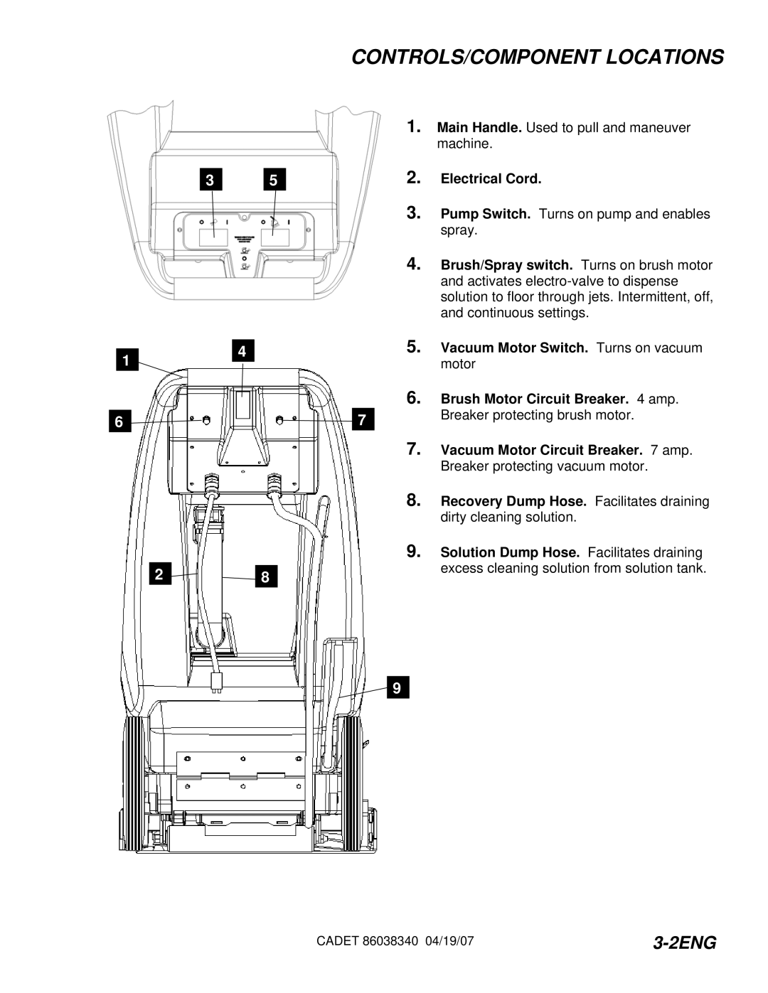
CDT7IB/10080060, CDT7IE/10080070, CDT7IA/10080050, CDT7IS/10080080 specifications
Windsor has established itself as a leader in the field of commercial cleaning equipment, with a particular focus on floor care. Among its notable offerings are the Windsor CDT7IE, CDT7IS, CDT7IA, and CDT7IB models. Each of these machines is designed to meet the varying needs of different cleaning environments, providing both versatility and efficiency.The CDT7IE model stands out with its exceptional ergonomic design, which enhances user comfort during prolonged cleaning tasks. It features advanced filtration technology that captures dust and allergens, making it ideal for healthcare environments and facilities requiring stringent cleanliness standards. Its powerful suction capabilities ensure optimal dirt and debris removal, while adjustable height settings allow for seamless transitions between different floor surfaces.
On the other hand, the CDT7IS is engineered with enhanced durability in mind, making it perfectly suited for high-traffic areas. This model is built with reinforced components that withstand the rigors of daily use, ensuring longevity and reliability. Additionally, it comes with an easy-to-use control panel, which simplifies operation for users of all skill levels. The CDT7IS also boasts a large-capacity dust bag, reducing the frequency of changes and allowing for longer cleaning intervals.
The CDT7IA model emphasizes versatility, as it is designed for various applications, including both hard and soft floor surfaces. Its dual-mode feature allows users to switch between deep cleaning and maintenance modes, providing flexibility for different cleaning needs. This model also integrates eco-friendly technologies, including energy-efficient motors that reduce power consumption without compromising performance.
Lastly, the CDT7IB model is specifically tailored for industrial and commercial use, featuring a rugged design that can tackle tough cleaning challenges. Its robust brush system provides excellent agitation on carpets, lifting dirt and grime effectively. The CDT7IB is not only powerful but also easy to maneuver, thanks to its low profile and lightweight construction.
Overall, each of the Windsor CDT7 models brings a unique set of features and technologies to the table, catering to the diverse requirements of the modern cleaning industry. Their combination of innovative design, advanced technologies, and user-focused features makes them reliable choices for professional cleaning tasks. Whether for healthcare, commercial, or industrial use, Windsor’s CDT7 series continues to uphold the brand's commitment to quality and performance in floor care.

