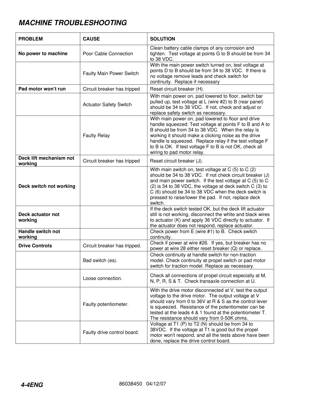
MACHINE TROUBLESHOOTING

PROBLEM

CAUSE

SOLUTION


No power to machine


Clean battery cable clamps of any corrosion and

Poor Cable Connection

tighten. Test voltage at points G to B should be from 34


to 38 VDC.


With the main power switch turned on, test voltage at


Faulty Main Power Switch

points D to B should be from 34 to 38 VDC. If there is


no voltage remove leads and check switch for


continuity. Replace if necessary

Pad motor won’t run

Circuit breaker has tripped

Reset circuit breaker (H).


With main power on, pad lowered to floor, switch bar


Actuator Safety Switch

pulled up, test voltage at L (wire #2) to B (rear panel)


should be 34 to 38 VDC. If not, check and adjust or


replace safety switch as necessary.


With main power on, pad lowered to floor and drive


handle squeezed: Test voltage at points F to B and A to


B should be from 34 to 38 VDC. When the relay is


Faulty Relay

working it should make a clicking noise as the drive


handle is squeezed. Replace relay if the test voltage F


to B is OK. If test voltage F to B is not OK, check all


wiring to pad motor relay.

Deck lift mechanism not

Circuit breaker has tripped

Reset circuit breaker (J).

working


With main switch on, test voltage at C (5) to C (2)


should be 34 to 38 VDC. If not check circuit breaker (J)

Deck switch not working


and main power switch. If the test voltage at C (5) to C


(2) is 34 to 38 VDC, the voltage at deck switch C (3) to


C (6) should be 34 to 38 VDC when the deck switch is


pressed to raise/lower the pad. If not, replace deck


switch.

Deck actuator not


If the deck switch tested OK, but the deck lift actuator


still is not working, disconnect the white and black wires

working


to actuator (K) and apply 36 VDC directly to actuator. If


the actuator does not respond, replace actuator.

Handle switch not


Check power from E (wire #1) to B. Check switch

working


continuity.

Drive Controls

Circuit breaker has tripped.

Check if power at wire #26. If yes, but breaker has no

power at wire 28 either reset breaker (Q) or replace.


Check continuity at handle switch for non-traction


Bad switch (es).

model. Check continuity at propel switch or pad motor


switch for traction model. Replace as necessary.


Loose connection.

Check all connections of propel circuit especially at M,


N, P, R, S & T. Check transaxle connection at U.


With the drive motor disconnected at V, test the output


voltage to the drive motor. The output voltage at V


Faulty potentiometer.

should vary from 0 to 36V at R & S as the control lever


is squeezed. Resistance of the potentiometer can be


tested at the leads 4 & 1 found at the potentiometer T.


The resistance should vary from 0-50K ohms.


Voltage at T1 (P) to T2 (N) should be from 34 to


Faulty drive control board.

38VDC. If the voltage at T1 is good but the propel


motor won't respond, and all the tests above have been


done, replace the drive control board.

4-4ENG

86038450 04/12/07

Page 12
Image 12
Windsor L20T, 10027110, 10027100 manual Machine Troubleshooting, Problem Cause Solution

10027110, L20, 10027100, L20T specifications

Windsor 10027110, L20, 10027100, and L20T are advanced heating and cooling systems designed to deliver efficient climate control in various settings. These models incorporate innovative technology and well-considered engineering features that make them stand out in the market.

One of the main features of these units is their energy efficiency. With rising energy costs and increasing environmental concerns, Windsor has focused on creating systems that minimize energy consumption while maximizing performance. The use of high-efficiency compressors and advanced heat exchange technology ensures that energy is used effectively, significantly reducing operating costs.

The Windsor 10027110 model, in particular, features a user-friendly interface that allows for easy temperature adjustments and programming. Users can easily manage their comfort settings, which further enhances the system's efficiency. The systems have the capability for precise temperature control, ensuring that spaces remain comfortable without unnecessary energy expenditure.

In terms of technology, these models are equipped with advanced inverter technology. This technology allows the units to adjust their power output according to the cooling or heating demand. By maintaining optimal performance without the usual energy spikes, inverter technology contributes to lower energy bills and a reduced carbon footprint.

Another notable characteristic of these Windsor systems is their durability and reliability. Built with high-quality materials and engineering processes, these units are designed to withstand the rigors of daily use in various climates. Regular maintenance and servicing can further extend their lifespan, making them a sensible long-term investment for homeowners and businesses alike.

Moreover, the Windsor L20 and L20T models are designed with noise reduction features, ensuring that they operate quietly. This is particularly beneficial in residential areas or in settings where a peaceful environment is paramount.

In conclusion, the Windsor 10027110, L20, 10027100, and L20T heating and cooling systems epitomize a perfect blend of efficiency, technology, and durability. Their user-friendly features and advanced engineering make them ideal solutions for individuals and businesses looking to optimize their climate control solutions while being mindful of energy consumption. These systems not only enhance comfort but also contribute positively to overall cost and environmental impact.