6
4 5
1
18
26
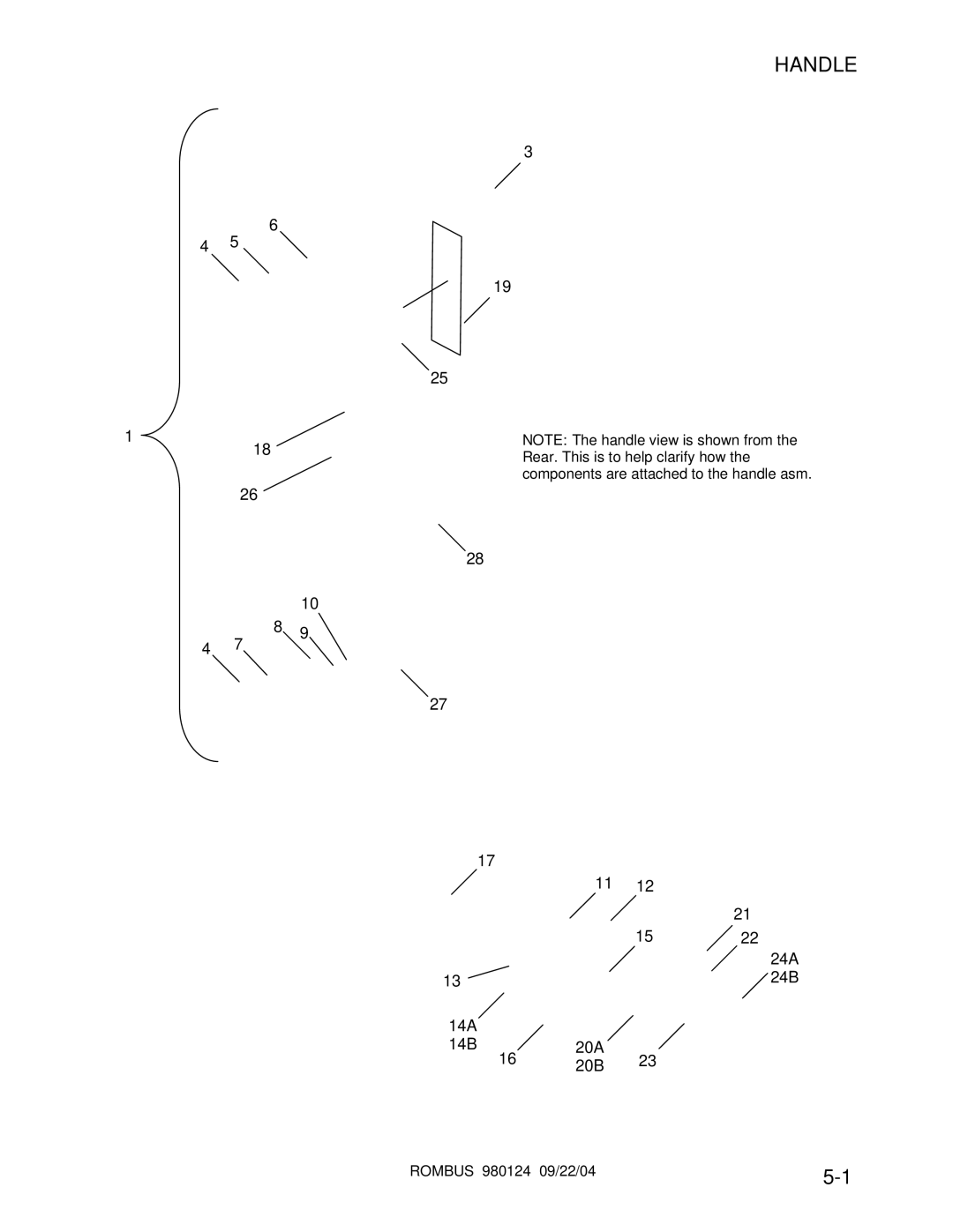
HANDLE
3
19
25
NOTE: The handle view is shown from the Rear. This is to help clarify how the components are attached to the handle asm.
28
4 7
10
8 9
27
| 17 |
|
|
|
|
|
|
|
|
|
|
|
|
|
|
| |||
|
|
|
|
|
|
|
|
|
|
|
|
|
|
|
|
|
|
|
|
|
|
|
|
|
|
| 11 |
|
|
|
|
|
|
|
|
|
|
| |
|
|
|
|
|
|
|
| 12 |
|
|
|
|
|
|
| ||||
|
|
|
|
|
|
|
|
|
|
|
|
|
|
|
|
|
|
|
|
|
|
|
|
|
|
|
|
|
|
|
|
|
|
|
|
|
|
|
|
|
|
|
|
|
|
|
|
|
|
|
|
| 21 |
|
|
| |||
|
|
|
|
|
|
|
|
|
|
|
|
|
|
|
|
|
|
|
|
|
|
|
|
|
|
|
|
| 15 |
|
|
|
|
| |||||
|
|
|
|
|
|
|
|
|
| 22 |
|
| |||||||
|
|
|
|
|
|
|
|
|
|
|
|
|
|
|
|
|
|
|
|
|
|
|
|
|
|
|
|
|
|
|
|
|
|
|
|
|
|
|
|
|
|
|
|
|
|
|
|
|
|
|
|
|
|
|
|
|
|
| 24A |
|
|
|
|
|
|
|
|
|
|
|
|
|
|
|
|
|
|
| 24B |
13 |
|
|
|
|
|
|
|
|
|
|
| ||||||||
|
|
|
|
|
|
|
|
|
|
|
|
|
|
|
|
|
|
|
|
| 14A |
|
|
|
|
|
|
|
|
|
|
|
|
| |||||
| 14B |
|
|
| 20A |
|
|
|
|
|
|
|
|
|
|
| |||
|
| 16 |
|
|
|
|
|
|
|
|
|
|
| ||||||
|
|
|
|
| 23 |
|
|
|
|
|
|
| |||||||
|
|
|
| 20B |
|
|
|
|
|
|
|
| |||||||
|
|
|
|
|
|
|
|
| |||||||||||
|
|
|
|
|
|
|
|
|
|
|
|
| |||||||
|
|
|
|
|
|
|
|
|
|
|
|
|
|
| |||||
ROMBUS 980124 09/22/04 | |
|
6
4 5
1
18
26
3
19
25
NOTE: The handle view is shown from the Rear. This is to help clarify how the components are attached to the handle asm.
28
4 7
10
8 9
27
| 17 |
|
|
|
|
|
|
|
|
|
|
|
|
|
|
| |||
|
|
|
|
|
|
|
|
|
|
|
|
|
|
|
|
|
|
|
|
|
|
|
|
|
|
| 11 |
|
|
|
|
|
|
|
|
|
|
| |
|
|
|
|
|
|
|
| 12 |
|
|
|
|
|
|
| ||||
|
|
|
|
|
|
|
|
|
|
|
|
|
|
|
|
|
|
|
|
|
|
|
|
|
|
|
|
|
|
|
|
|
|
|
|
|
|
|
|
|
|
|
|
|
|
|
|
|
|
|
|
| 21 |
|
|
| |||
|
|
|
|
|
|
|
|
|
|
|
|
|
|
|
|
|
|
|
|
|
|
|
|
|
|
|
|
| 15 |
|
|
|
|
| |||||
|
|
|
|
|
|
|
|
|
| 22 |
|
| |||||||
|
|
|
|
|
|
|
|
|
|
|
|
|
|
|
|
|
|
|
|
|
|
|
|
|
|
|
|
|
|
|
|
|
|
|
|
|
|
|
|
|
|
|
|
|
|
|
|
|
|
|
|
|
|
|
|
|
|
| 24A |
|
|
|
|
|
|
|
|
|
|
|
|
|
|
|
|
|
|
| 24B |
13 |
|
|
|
|
|
|
|
|
|
|
| ||||||||
|
|
|
|
|
|
|
|
|
|
|
|
|
|
|
|
|
|
|
|
| 14A |
|
|
|
|
|
|
|
|
|
|
|
|
| |||||
| 14B |
|
|
| 20A |
|
|
|
|
|
|
|
|
|
|
| |||
|
| 16 |
|
|
|
|
|
|
|
|
|
|
| ||||||
|
|
|
|
| 23 |
|
|
|
|
|
|
| |||||||
|
|
|
| 20B |
|
|
|
|
|
|
|
| |||||||
|
|
|
|
|
|
|
|
| |||||||||||
|
|
|
|
|
|
|
|
|
|
|
|
| |||||||
|
|
|
|
|
|
|
|
|
|
|
|
|
|
| |||||
ROMBUS 980124 09/22/04 | |
|