HANDLE INSTALLATION
4
5 ![]()
DECK
ASSEMBLY ![]()
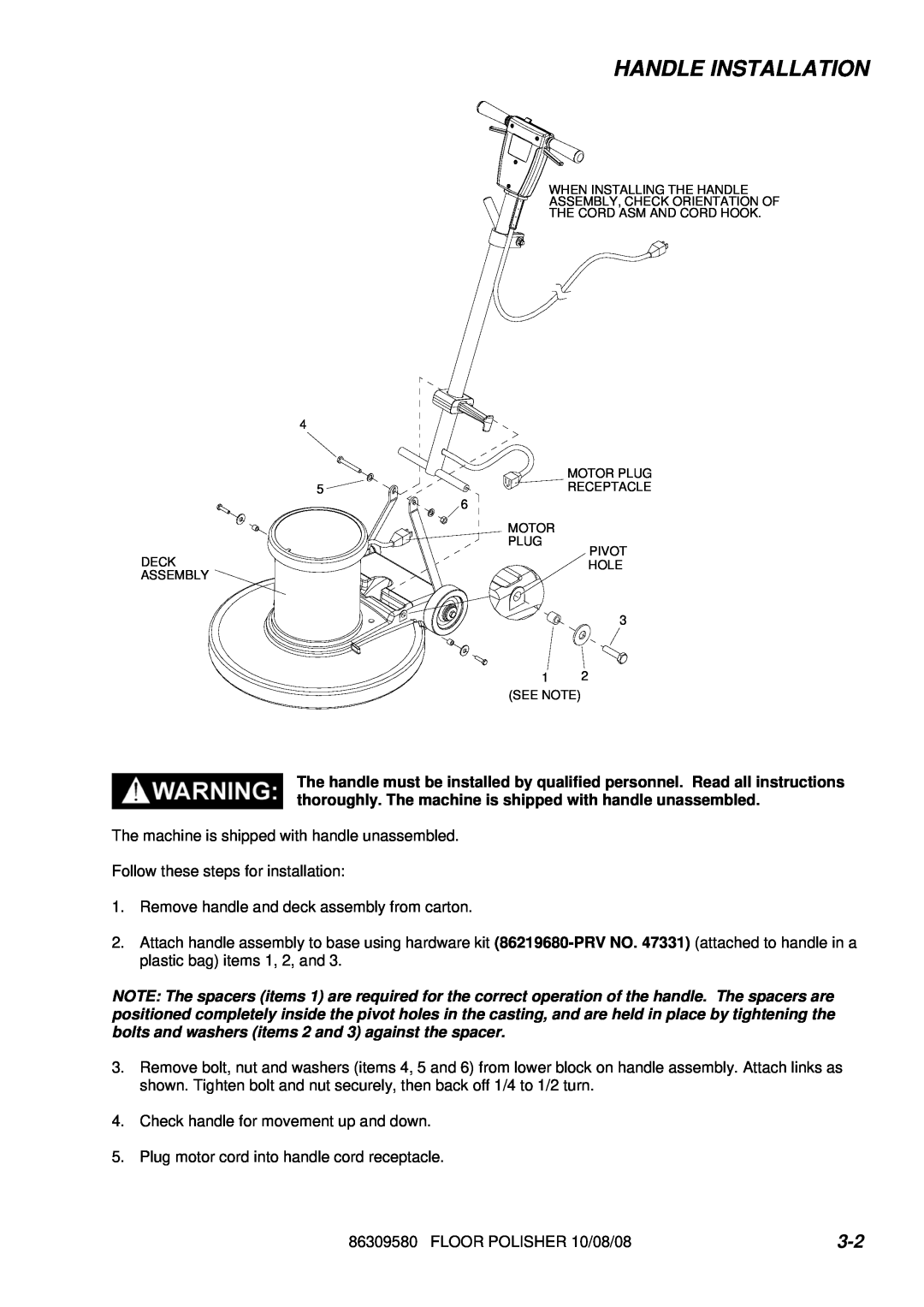
WHEN INSTALLING THE HANDLE
ASSEMBLY, CHECK ORIENTATION OF
THE CORD ASM AND CORD HOOK.
MOTOR PLUG
![]()
![]()
![]() RECEPTACLE
RECEPTACLE
6
MOTOR
PLUG
PIVOT
HOLE
3
12
(SEE NOTE)
The handle must be installed by qualified personnel. Read all instructions thoroughly. The machine is shipped with handle unassembled.
The machine is shipped with handle unassembled.
Follow these steps for installation:
1.Remove handle and deck assembly from carton.
2.Attach handle assembly to base using hardware kit
NOTE: The spacers (items 1) are required for the correct operation of the handle. The spacers are positioned completely inside the pivot holes in the casting, and are held in place by tightening the bolts and washers (items 2 and 3) against the spacer.
3.Remove bolt, nut and washers (items 4, 5 and 6) from lower block on handle assembly. Attach links as shown. Tighten bolt and nut securely, then back off 1/4 to 1/2 turn.
4.Check handle for movement up and down.
5.Plug motor cord into handle cord receptacle.
86309580 FLOOR POLISHER 10/08/08 |